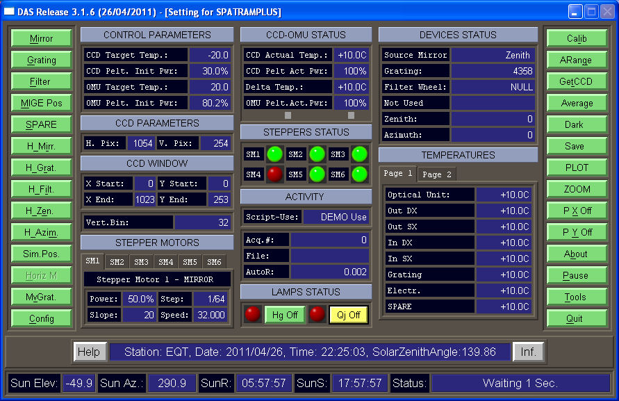
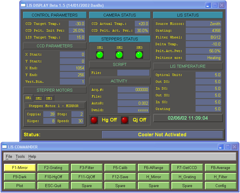
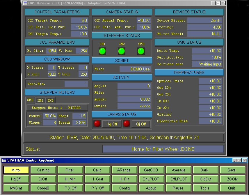
The DAS GUI has been suffered many upgrades in the last years. DAS GUI Previous versions have less controls and different disposition of the main windows
The DAS main panel actually adopted is the one shown below.
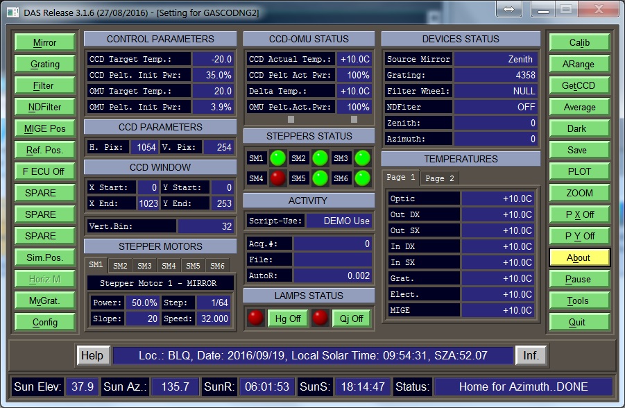
From Left to Right can be identified 5 column forms:
- Push Buttons (Left Column)
- Optical Mechanical Unit (OMU) Parameters
- Optical Mechanical Unit (OMU) Status
- Optical Mechanical Unit (OMU) Status 1
- Push Buttons (Right Column)
And below the column forms there are:
More About
<CENTER>**********************************************************************</CENTER>
<CENTER>--------------- START LEFT PUSH BUTTONS SECTION   --------------------</CENTER>
<CENTER>**********************************************************************</CENTER>
Push Buttons (Left Column)
Commands
The commands in the first column provide mainly for the movements of the devices linked to the stepper motors.
- Mirror - Set the input mirror position (SD_Mirror function)
- Grating - Set the grating position (SD_Grating function)
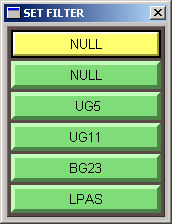
- Filter Wheel - Set the filter wheel position (SD_FilterW function)
- Neutral Density Filters - Set the position of the Neutral Density filter(s) - depending on the type of installed device/n
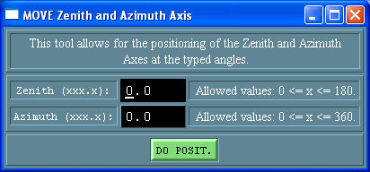
- MIGE Pos - Set the zenith and Azimuth axes position of the MIGE device (MDCreateMoveZenAzimDeg function)
- - Reference position - Reference position for the mooving devices
- - Fan ECU - Switch on/off the electronic fans (available only on GASCODNG1 instrument (in Antarctica).

- SPARE - SPARE
- SPARE - SPARE
- SPARE - SPARE
- Sim.Pos. - Create the window for for testing the motion of the mechanical devices (MDCreateSh_SimPos)
- Horiz M - Create the window allowing to perform horizontal measurements in manual mode(MDCreateHorMeas)
- MvGrat - Set the grating position with a free number of steps (MDCreateMoveGrat)
- DAS Configuration Panel - Open the DAS Config panel (MDCreateDASConfig)
All the buttons have the same callback (DB_KeyB_CB) with different values for the calling parameter (namely the index in the command button array)
Back to DAS MAIN Graphic User Interface
Back to main
"+++++++++++++++++++++++++++++++++++++++++++++++++++++++++++++++++++++"
Mirror

At the pression of the Mirror button the corresponding shell is created and the user can select the desired position for the mirror
Depending on the instrument type () a different shell is showed
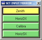
| Position | Code |
| Zenith | 0 |
| Horiz DX | 1 |
| Calibra | 2 |
| Horiz SX | 3 |
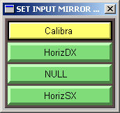
| Position | Code |
| Calibra | 0 |
| Horiz DX | 1 |
| NULL | 2 |
| Horiz SX | 3 |
Back to mainpage
Grating

At the pression of the Grating button the corresponding shell is created and the user can select the desired position for the grating
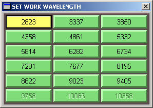
| Position (A) | Code | Position (A) | Code | Position (A) | Code |
| 2823 | 0 | 3337 | 1 | 3850 | 2 |
| 4358 | 3 | 4861 | 4 | 5332 | 5 |
| 5814 | 6 | 6282 | 7 | 6734 | 8 |
| 7201 | 9 | 7677 | 10 | 8195 | 11 |
| 8622 | 12 | 9023 | 13 | 9405 | 14 |
| 9758 | 15 | 10066 | 16 | 10358 | 17 |
Until DAS306 the spectral windows were fixed and only with source code modifications should be possible to modify the Central Wavelength/steps and consequently the spectral windows of measurements.
Starting from DAS307 to DAS315 it is possible to modify the number of steps, but not the Central Wavelengths.
Moreover the Reference Position (4358 A, step = 0, with ID = 3) is fixed, forcing to have only 3 more window in the UV (2823, 3337, 3850).
With DAS316 and following, the Central wavelength and the steps can be modified In addition using the function LookforWl_X, it is now possible to assign the reference position 435.8 nm to any ID. If the reference position 4358 A, step = 0 has ID = 5,
I can Add 2 more spectral window in the UV region for example (2823, 3132, 3337, 3650, 3850).
This can be obtained:
- using the graphic interface in "Config–>Parameter–>Page 2
- modifying directly the wlstep file in the equipment config directory
- with a standard text editor
- with the embedded MGUI text editor in "Config–>Options–>Options - Page 2
After these modifications the windows for the wavelength positioning will be:
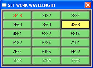
Note the presence of the 2 new spectral windows centered in the 3132 and 3650A.
NOTE 1 - the 435.8 has to have step = 0 and the steps towards the UV must be negative (towards the visible positive)
NOTE 2 - The step values listed in the wlstep file, are NOT the real steps executed by the grating stepper motors, since the steps have been parametrized in order to allow for the modification of the motor settings (AMS Steps/round) without any change in the wlstep file. The parametrization take into account the capabilities of the AMS2 (Advanced Micro Stepping) Controller to apply the microstepping technology. The DAS encoding procedure is located in the SD_Grating function. Also the mechanical reduction (mr=4) of the grating positioning device is taken into account.
In practice:
![\[ StepsExec(t(i)) = StepF * (AMS_StepR(t(i))/3200)* mr \]](form_0.png)
with:
 = Fractioning of the motor stepping (microsteps) for i =0,1,...13. (AMS Steps/round);
 = Steps executed by the stepper motor;
 = Steps read in the wlstep.ini file;
 =AMS Steps/round =
  (200 step/round is the nominal value for a standard stepper motor);
 = mechanical reduction = 4;
 = Normalisation Factor (NormFac);
In the table below is reported an example with StepF = 12180 as read in the wlsteps.ini file
| i | t | AMS_StepR(t) | NormFac | AMS_StepR(t)/NormFac | mr | StepF | StepsExec(t) |
| 0 | 2 | 400 | 3200 | 0.125 | 4 | 12180 | 6090 |
| 1 | 4 | 800 | 3200 | 0.25 | 4 | 12180 | 12180 |
| 2 | 5 | 1000 | 3200 | 0.3125 | 4 | 12180 | 15525 |
| 3 | 8 | 1600 | 3200 | 0.5 | 4 | 12180 | 24360 |
| 4 | 10 | 3000 | 3200 | 0.625 | 4 | 12180 | 30450 |
| 5 | 16 | 3200 | 3200 | 1.0 | 4 | 12180 | 48720 |
| 6 | 25 | 5000 | 3200 | 1.5625 | 4 | 12180 | 76125 |
| 7 | 32 | 6400 | 3200 | 2 | 4 | 12180 | 97440 |
| 8 | 50 | 10000 | 3200 | 3.125 | 4 | 12180 | 152250 |
| 9 | 64 | 12800 | 3200 | 4.0 | 4 | 12180 | 194880 |
| 10 | 125 | 25000 | 3200 | 7.8125 | 4 | 12180 | 380625 |
| 11 | 128 | 25600 | 3200 | 8.0 | 4 | 12180 | 389760 |
| 12 | 250 | 51000 | 3200 | 15.625 | 4 | 12180 | 761250 |
| 13 | 256 | 51200 | 3200 | 16.0 | 4 | 12180 | 779520 |
For more info and options please refer to MvGrat
Back to main
Filter Wheel

At the pression of the Filter button the corresponding shell is created and the user can select the desired position for the Filter Wheel
Back to main
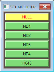
Neutral Density Filters

Depending on the Filter module installed on the instrument this push button presents different behaviors:
- if the PLUS module is installed, pushing the button insert the only filter available driven by a torque motor. The SM4 led became green and the NDFilter label show "ON". The instrument equipped with the PLUS module are: GASCODNG1 and GASCODNG2
- if the DOUBLE module is installed (SPATRAMPLUS, SPATRAM2, SPATRAM3), the shell allowing to choose the neutral density filter to insert is displayed./
Back to main
MIGE Pos

Back to main
- Reference position

Pushing the button the reference position shell is displayd,
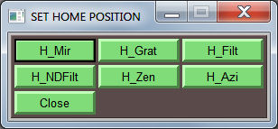
At the selection of one of the device, its the reference position is reached. The Devices are:
- Input Mirror (Zenith for LIS, SPATRAMPLUS, SPATRAM2, SPATRAM3, GASCODNG1, NG2, NG3; Calibra for TROPOGAS, NG4)
- Grating (about 435.8 nm)
- Filter Wheel (NULL)
- Neutral density Filter Wheel (NULL)/Torque motor (OFF)
- MIGE Zenith Axis
- MIGE Azimuth Axis
Back to DAS MAIN Graphic User Interface
Back to main+++++++++++++++++++++++++++++++++++++++++++++++++++++++++++++++++++++
- Fan ECU
Switch on/off the electronic fans (available only on GASCODNG1 instrument (in Antarctica).

Back to main
SPARE
Available for future improvements.

Back to main
H_Mir

At the pression of the H_Mirr button the reference position for the input mirror is reached

Back to main
H_Grat

At the pression of the H_Grat button the reference position for the grating is reached

Back to main
H_Filter

At the pression of the H_Filter button the reference position for the Filter Wheel is reached

Back to main
H_Zenith

At the pression of the H_Zenith button the reference position for the Zenith Axis is reached

Back to main
H_Azim

At the pression of the H_Azim button the reference position for the Azimut Axis is reached

Back to main
MvGrat

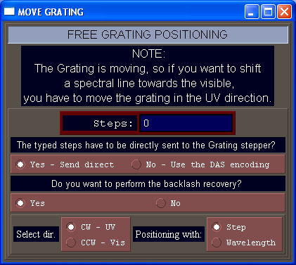
The MOVE GRATING tool allow for the movement of the grating towards the UV or Visible directions of a free number of steps or (approximatively) of the typed wavelengths (A) The different options are:
- Steps sending mode:
- directly to the motor (The stepper motor will execute exactly the number of typed steps)
- trough the DAS parametrization (Grating)
- Backlash recovery (Recupero del gioco!!!!!!)
- Yes - When the grating moves in the UV direction a fixed amount of steps (500) is added to the typed ones and after the positioning the same 500 steps are performed in the opposite direction.
- No - The grating moves without performing the backlash recovery
- Direction selection
- UV
- Visible
- Positioning Mode
- Steps
- Wavelength (A)
This tool can be used in order to determine the steps the motor of the grating has to perform to reach a specified position.
To semplify this operation the 2 commands READ Grat. Steps and ZERO Grat. Steps in the Tools, can be used.
Back to main
Sim.Pos.

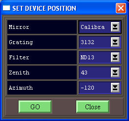
With this window is possible to set the position of the different device of the instrument
Back to main
Horiz M

Create a new Window for the horizontal measurements (available only for old realise of GASCODNG1)

Back to main
Optical Mechanical Unit (OMU) Parameters
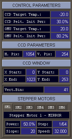
The DAS frame OMU Parameters contains informations loaded at the Booting of DAS from the Param.ini and AMS.INI files.
- CONTROL PARAMETERS
- CCD Target Temp.: Target Working temperature for the CCD Camera
- CCD Pelt.Init Pwr:Initial power assigned to the Peltier's CCD
- OMU Target Temp: Target working temperature for the Optical Mechanical Unit
- OMU Pelt. Int Pwr:Initial power assigned to the OMU's CCD
CCD PARAMETRS: Horizontal and Vertical pixels of the CCD sensor (this information is retrieved directly from the DCL Library
- CCD WINDOW: Coordinate of the CCD used for the acquisition of image and applied Vertical Binning
- STEPPER MOTORS: Power (), step fractioning (AMS Steps/round), slope () and speed-frequency ()for each motor managed by DAS with AMS2 (Advanced Micro Stepping) Controller
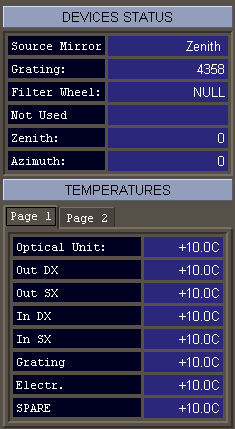
Optical Mechanical Unit (OMU) Status
Optical Mechanical Unit (OMU) Status 1
Push Buttons (Right Column)
The second column of commands provide mainly for the measurements
- Calib - Spectral calibration (D_Calibra)
- Arange - Computation of the optimum Exposure Time(AutoRange)
- GetCCD - Acquisition of the image (single measurement) (DB_GetCCD)
- Average - Acquisition of the image (multiple measurements) (D_Average)
- Dark - Acquisition of the DARK image (DB_GetCCD)
- Save - Saving the measured spectrum (D_Saving)
- PLOT - Plots the spectrum (ViewPlot)

- ZOOM - Zoom of the image (DI_Lens)
- P X Off - X Profile Active\Inactive (D_XProfile)
- P Y Off - X Profile Active\Inactive (D_YProfile)
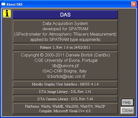
- About - The About window is displayed(AboutCB)
- Pause - Pause\Resume the PRG file in execution (DB_Pause)
- Tools - The tool keyboard is displayed (DB_Tools)
- Quit - Show the ShutDown window (ShutDOWN)
+++++++++++++++++++++++++++++++++++++++++++++++++++++++++++++++++++++
Calib

Perform the spectral calibration at 435.8 nm with the internal HG spectral lamp
The calibration procedure provide the positioning the HG spectral line in the centre (512 +/ 1 pixel) of the CCD sensor.
If the grating position is not the default for calibration (435.8 nm) DAS aware of this situation and the window below is shown.

The user can choose to:
- Continue the calibration procedure even not in the default spectral window
- Position the grating in the default spectral window and then perform the calibration
- Cancel the calibration procedure
+++++++++++++++++++++++++++++++++++++++++++++++++++++++++++++++++++++
Arange

The autoranging procedure is one of the most important DAS's functions since it calculate the optimum exposure time for the measurements in order to:
- obtain the highest SNR ( for situation with low energy of the incident radiation )
- prevent the CCD satuaration ( for situation with high flux of radiation.
The autoranging procedure can calculate the optimal exposure time with or without the shutter installed.
With the Shutter system installed and until realise 3.1.5 the Exposure Time (TExp) is calculated with a very simple and empirical formula:
![\[ TExp = \frac{LEVEL * TExpAR} {Max(TExpAR) - Min(TExpAR)} \]](form_8.png)
with:
- LEVEL = Maximum Target of the measurement (usually 55000 Digital Counts)
- TExpAR = Exposure time of autoranging used to carry out the test measurement (= 0.1 s)
- Max(TExpAR) = Maximum value of the Test Measurement
- Min(TExpAR) = Minimum value of the Test Measurement
The previous expression is valid mainly for measurements of spectral lamp radiation where the the difference between Max and Min is very high due to the presence of the spectral lines. For measurements of scattered solar radiation and for the different offsets of the CCDs Equipping the Instrument maneged with DAS, additional terms has to be sometimes added or subtracted to the previous equation.
The procedure can be summarized with:
After the first measurement with the TExpAR exposure time, the obtained signal is checked:
- if Max(TExpAR) > LEVEL then DAS enter a DO cicle decreasing the TExpAR until when it is lower than the Minimum Exposure time (TExpMin) allowed
- If TExpAR <= TExpMin then the Neutral Density (ND - usually ND2) filter is positioned for the test measurement
- if Max(TExpAR) < LEVELINF (LEVELINF = 4000 digital counts) then DAS enter a DO cicle increasing the TExpAR until when the LEVELINF is reached in order to be sure to measure something. Actually this DO cycle is repeated 4 or 5 times for a TExpAR maximum of about 5 s
If the shutter is not installed the minimum exposure time depends on the CCD Reading Time (RT). This last is function of the binning parameters and for the HIRES_IV CCD driver, it can be calculated according to the formula:
![\[ RT = \frac{vp}{vb}·Kv + \frac{vp}{vb}·\frac{hp}{hb}·Kh \]](form_69.png)
where:
- RT = reading time (in ms)
- vp = vertical pixels number
- vb = vertical binning
- Kv = 0.024 for hires
- hp = horizontal pixels number
- hb = horizontal binning
- Kh = 0.0125
For High values of Vertical Binning RT is very short (i.e for VertBin of41-the maximum supported by HiRESIV-RT is less than 0.09 sec) therefore the excess of signal due to the over-exposition of the sensor can be neglected.
Therefore, for measurements without the shutter installed, the minimum exposure time (TEexpMin ) allowed is depending mainly on the vertical binning and on the radiatin flux. The TExpMin is fixed as the double of the RT
![\[ TExpMin = 2 * (\frac{vp}{vb}·Kv + \frac{vp}{vb}·\frac{hp}{hb}·Kh) \]](form_70.png)
This approach is still under testing phase, so to obtain the best results it is still advisable the use of the equipment with the shutter installed.
One of the factors manly affecting the autoranging procedure is the type of shutter used to carry out the spectral measurements. At the beginning of the equipment development the Uniblitz mod.:VS25 shuttering system was adopted. This is a very fast system (the opening and closing phases of about 5ms each one) allowing for the neglection of the influence of the signal received by the CCD during the transient periods. The main problem with the VS25 is the limitation of 1.000.000 (un million) of ensured shuts. Taking into account the high frequency of the measurements, (the one million of shuts are reached in 2 months of instrument 12h operation) it was necessary to change the shuttering system.
Two new shutter systems were developed:
- The rotating shutter - ROTSHUT - based on a rotating wheel with 4 equi-spatied holes actuated with a stepper motor driven by a SSC controller. This system is slower than the VS25 (45ms against the 5ms of the VS25), but more durable. the main disadvantage of this model is the increased number of wirings to be set-up in the monocromator and in the ECU.
- The flagging shutter - TORQUEM - based on a torque motor acting on a flag. This is simpler than the ROTSHUT (the TORQUEM use the same wiring of the VS25), but it's not still fully tested (07/02/2011)
The studies on the capabilities and on the behaviour of the VS25 and ROTSHUT systems suggested the implementation of a new Autoranging procedure. The procedure implemented and used starting from DAS 3.1.6, is based on the linearity of the CCD charge with exposure time according to the formula:
![\[ Y = m·X \]](form_71.png)
where:
- Y = CCD Signal (digital counts)
- m = slope
- X = Exposure Time (TExp)
since m is:
![\[ m = \frac{Y2 - Y1}{X2 - X1} \]](form_12.png)
the exposure time TExp can be calculated according to the formula:
![\[ TExp = LEVEL ·\frac{TExpAR - TExpMin}{Max(TExpAR) - Max(TExpMin)} \]](form_72.png)
where:
- LEVEL = Maximum Target of the measurement (digital counts)
- TExpAR = Autoranging time (X2)
- TExpMin = Minimum Exposure Time (X1)
- Max(TExpAR) = Maximum signal obtained for Autoranging Exposure time (Y2)
- Max(TExpMin) = Maximum signal obtained for Minimum Exposure Time (Y1)
The new autoranging procedure (adopted for DAS316 ) can be summarized with:
- the first measurements is performed with the TExpMin
- If Max(TExpMin) > LEVEL then the Neutral Density filter is positioned
- The measurement with TExpMin is repeated and the 'zero' value is determined
- A measurement with a fixed TExpAR time is carried out
- If Max(TExpAR) > LEVEL then DAS enter a DO cicle decreasing the TExpAR until when it is minimum the double of TExpMin
- if again Max(TExpAR) > LEVEL then the Neutral Density filter is positioned if not already present
- the whole procedure is repeated
- if Max(TExpAR) < LEVELINF (LEVELINF = 4000 digital counts) then DAS enter a DO cicle increasing the TExpAR until when the LEVELINF is reached in order to be sure to measure something. Actually this DO cycle is repeated 4 or 5 times for a TExpAR maximum of about 5 s
- The TExp is calculated
- Some additional controls checking the validity of the calculate exposure time are performed
GetCCD


Perform a single measurements for the specified exposure time
Average

Perform an averaged measurement.
Following what is setted in the DAS_Config–>Option–>Page1–>AVERAGING section, the averaging can be executed with different options:
Automatic Autoranging
- Yes: the autoranging is performed before the measurement and the calculated exposure time value is used for all the measurements.
- No: the autoranging is NOT performed so the last autoranging time or the specified one (in case of automatic measurements) is used. If the exposure time is zero (if DAS is just initiated and no measurement is carried out yet) the user is awared of this situation and the procedure is interrupted.
- Fix TExp: the measurements are averaged since the Total TExp setted in the edit field is reached (the number of measurements is automatically calculated
- Fix Meas. Numb.: the number of averaged measurements is specified in the edit field
Dark

Get a dark image for the specified exposure time

Save

Save the spectral measurement on the PC.
The format and location of the svaed measurements depend on the SAVING option in DAS Config–> Options - Page 1 .
+++++++++++++++++++++++++++++++++++++++++++++++++++++++++++++++++++++
PLOT

DAS plots the last acquired spectrum
ZOOM

P X Off


P Y Off


About

Pause


Tools
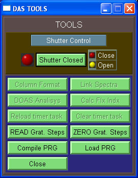
The Tool keybord is partially greyed since some of the function are currently on progress.

The available buttons allows for some additional commands:
- READ Grat. Steps read the step actually performed by the grating stepper motor (without any parametrization (Grating)
- ZERO Grat. Steps set to zero the steps performed by the grating stepper motor at the actual position
- Compile PRG allows to check the syntax of a PRG file
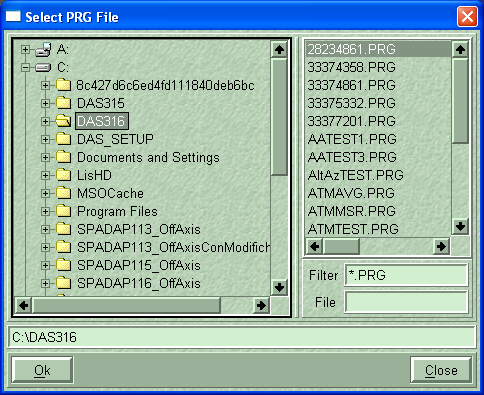
- Load PRG allows to select a new PRG file to be executed
NOTE - Even if the Browser open by the Load PRG let to load also files with different extensions (modifying the filter *.PRG) only the PRG files can be loaded and only when DAS is running in PRGFILE or MANUAL modes
Quit

Allows for the selection of quitting DAS:
- F1 - CCD ShutDown, Cooler ON
- F2 - CCD ShutDown, Cooler OFF
- F3 - NO CCD ShutDown, Cooler ON
- F4 - NO CCD ShutDown, Cooler OFF
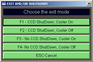
+++++++++++++++++++++++++++++++++++++++++++++++++++++++++++++++++++++ ********************************************************************** ------------— END RIGHT PUSH BUTTONS SECTION -----------------— **********************************************************************
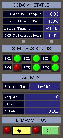
1st Status Label

2st Status Label

If the initialization of the CCD Camera give a positive result, also the CCD image and the CCD histogram are loaded
otherwhise a message error is displayed

Also the AMS devices are initialized and if they are not found a message dialog appears


Finally the AD_Converter (the PC104) is initalized and if there are problems a message dialog appears

DAS History.
The main features of the implementation of DAS are listed
- 0.5.0 - 15/10/2001 - First Graphic User Interface:DAS Control panel (DCP) & Command Keyboard (CK) DTA - Pisa
- 0.6.0 - 06/11/2001 - Added Stepper Motors Leds to DCP - Evora
- 0.7.0 - 20/11/2001 - Added Lamps Leds to DCP- Evora
- 0.8.0 - 23/12/2001 - DAS-Config Panel (DCfg) - Colors and Fonts pages
- 0.9.0 - 07/01/2002 - Mirror movement
- 1.0.0 - 18/02/2002 - Grating movement
- 1.0.1 - 25/02/2002 - Filter movement
- 1.0.2 - 03/03/2002 - Plot window - For on line data!!
- 1.0.3 - 16/03/2002 - ZOOM on Image Tool
- 1.0.4 - 17/03/2002 - XY Profile on Image
- 1.0.5 - 18/03/2002 - GetCCD Procedure
- 1.0.6 - 19/03/2002 - Calibration Procedure
- 1.0.7 - 20/02/2002 - AutoRange Procedure
- 1.0.8 - 21/02/2002 - Home mirror procedure
- 1.0.9 - 22/02/2002 - Home grating procedure
- 1.1.0 - 23/02/2002 - Home filter wheel procedure
- 1.1.1 - 24/03/2002 - Errors CCD
- 1.1.2 - 25/03/2002 - Errors AMS
- 1.1.3 - 26/03/2002 - Errors DMM (PC104 for temperatures)
- 1.1.4 - 27/03/2002 - Calculation of Solar Angles procedures added
- 1.1.5 - 28/03/2002 - Move Grating of a free number of steps
- 1.1.6 - 29/03/2002 - DCfg - Saving Mode Option
- 1.1.7 - 30/03/2002 - DCfg - File Name & type of image Options
- 1.1.8 - 03/04/2002 - DCfg - Dark Image Option
- 1.1.9 - 05/04/2002 - DCfg - Param page - CCD & OMU Temp, CCD Window
- 1.2.0 - 07/04/2002 - DCfg - Param page - CCD Setup Button
- 1.2.1 - 09/04/2002 - DCfg - Stepper motor page - Stepper parameters
- 1.2.2 - 10/04/2002 - ASCII Saving procedure
- ...............................................
- ...............................................
- 2.0.5 - 19/08/2002 - Release for Lampedusa Island Spectrometer
- 2.0.6 - 24/01/2003 - DCfg - Stepper motor page - Test Relais
- 2.0.7 - 25/01/2003 - DCfg - Options page - Defective pixel Correction
- 2.0.8 - 26/01/2003 - DCfg - Options page - CCD Target Temperature
- 2.0.9 - 27/01/2003 - DCfg - Options page - Configuration files section
- 2.1.0 - 28/01/2003 - DCfg - Options page - Plot options
- 2.1.1 - 29/01/2003 - DCfg - Options page - Plot options -Hidden lines & Blind Pixels
- 2.1.2 - 30/01/2003 - DCfg - Options page - SZA Limit
- 2.1.3 - 10/02/2003 - DCfg - Color page - Added "Load palette" button
- 2.1.4 - 11/02/2003 - DCfg - added "Test AD Converter" page
- 2.1.5 - 13/02/2003 - DCfg - Stepper motor page - Stepper parameters
- 2.1.6 - 15/02/2003 - Added AMS High Level Procedures: AMS_chkbitsts,AMS_Default,AMS_Power
- 2.1.7 - 19/02/2003 - Added AMS High Level Procedures:AMS_Step, AMS_Slope, AMS_Speed
- 2.1.8 - 02/03/2003 - Added AMS High Level Procedures:AMS_TrackOn, AMS_TrackOff, AMS_firmrev
- 2.1.9 - 03/03/2003 - Added AMS High Level Procedures:AMS_dirfin, AMS_DoPos,AMS_AzzeraCoord
- 2.2.0 - 05/03/2003 - Added AMS High Level Procedures:AMS_wopto, AMS_PWM,
- 2.2.1 - 12/03/2003 - Added D_LOG structure
- 2.2.2 - 22/03/2003 - ZOOM Procedures for spectral plot
- 2.2.3 - 10/04/2003 - Fixed bug on mirror and filter wheel movements
- 2.2.4 - 14/05/2003 - Added procedure for averaging on 'a priori' fixed time
- 2.2.5 - 03/07/2003 - Fixed bug on grating positioning (inversion direction)
- 2.2.6 - 05/07/2003 - Added Test PC104 AD Converter
- 2.2.7 - 09/07/2003 - Added Test Opto Ports AMS (for Relais)
- 2.2.8 - 11/07/2003 - Added new options pages (Plot, SZA, Config Files...
- 2.2.9 - 14/07/2003 - New Format of the PARAM.INI config file
- 2.3.0 - 01/08/2003 - New PLOT Window
- 2.3.1 - 02/08/2003 - Relsease for SPATRAM - FFT Filtering Procedures
- 2.3.2 - 03/08/2003 - DOAS module - CalcSpectrumLimits
- 2.3.3 - 22/08/2003 - switch for MAX/MIN - FULLRange for Y axis
- 2.3.4 - 07/09/2003 - switch for PIX-WL[A]-WL[nm] for X Axis
- 2.3.5 - 09/09/2003 - Added File Maneger Module
- 2.3.6 - 12/09/2003 - Added Print Shell capability
- 2.3.7 - 18/09/2003 - Added SZA limit in DAS Config->options->p3
- 2.3.8 - 27/09/2003 - Introduced new execution modes - OFFLINEPLOT, TESTAMS, TESTCCD, DEMO
- 2.3.9 - 21/10/2003 - added CCD Temp driven by SZA procedure
- 2.4.0 - 03/11/2003 - OnOffLinePlot Procedures
- 2.4.1 - 13/11/2003 - DIL 2.41 & MGUI 4.1.4 - New Tools on the main Command Keyboard
- 2.4.2 - 10/12/2003 - Calculating Flux Index procedures
- 2.4.3 - 12/12/2003 - Column format of the measurement files
- 2.4.4 - 13/12/2003 - Procedures for the file correction for shift of the CCD signal (DTA Bug)
- 2.4.5 - 15/12/2003 - New Format for the OPTIONS.INI, PALETTE.INI, GEOCOORD.INI config file
- 2.4.6 - 18/12/2003 - Introduction of the LOAD PALETTE button in DASConfig->Colors tab
- 2.4.7 - 14/11/2003 - New Header for measurements files
- 2.4.8 - 15/11/2003 - Added delay for shutter and computation of total integration time in avg measurements mode
- 2.4.9 - 19/11/2003 - Added EDIT module for config files
- 2.5.0 - 21/11/2003 - Added STORE Procedures for config files
- 2.5.1 - 28/11/2003 - Added "MAP Over/Under exposed pixels" procedures
- 2.5.2 - 03/12/2003 - Fixed bug for "DAS Config->Param->CCD Setup"
- 2.5.3 - 07/12/2003 - Introduced progression bars for Mirror, grating, filter positioning
- 2.5.4 - 22/01/2004 - Added new ShowDown-Digit shell
- 2.5.5 - 23/01/2004 - Unified OnOffLinePlot procedures
- 2.5.6 - 28/01/2004 - DB_ScanMaxMin with Blind pixels
- 2.5.7 - 29/01/2004 - Progression bar for Mirror, grating, filter homing
- 2.5.8 - 30/01/2004 - Fixed bug in D_Saving (change of the date). Added D_Calibra notification window
- 2.5.9 - 19/02/2004 - FFT Algorithms - Filter and Smoothing procedures
- 2.6.0 - 29/02/2004 - Fixed Bugs in DB_Ask - First DOAS Interface
- 2.6.1 - 12/03/2004 - Added DEMO Mode Capability (Autorange and download image DEMO)
- 2.6.2 - 06/04/2004 - Added PID in OMU Thermoregulation
- 2.6.3 - 13/04/2004 - Fixed bug on SZA Calculation at midnight in Daylight saving period
- 2.6.4 - 15/04/2004 - Fixed saving in Binary mode
- 2.6.5 - 22/04/2004 - Added DOAS execution mode, DOAS main Panel and GUI
- 2.6.6 - 15/05/2004 - BIN2ASCII and ASCII2BIN GUI and Procedure
- 2.6.7 - 18/06/2004 - 'Create List' GUI and algorithms
- 2.6.8 - 21/06/2004 - Fixed bug in PID algorithms
- 2.6.9 - 04/07/2004 - Added Automatic Data Back-UP via FTP Connection (GUI and procedures)
- 2.7.0 - 21/09/2004 - New Prograssive Algorithm (NEPAT) for OMU Thermoregulation
- 2.7.1 - 22/09/2004 - added FILO Buffer for temperatures
- 2.7.2 - 27/09/2004 - Fixed bug in NEPAT
- 2.7.3 - 29/09/2004 - New GUI adapted for TROPOGAS
- 2.7.4 - 03/10/2004 - Defined different type of instrument
- 2.7.5 - 06/10/2004 - Discrimination of different Hardware setting (COM port for AMS, Motor Direction for Grating, Home polarity and geometry for Filter wheel)for LIS, SPATRAM, GASCODNG, TROPOGAS
- 2.7.6 - 11/10/2004 - Added OMU Power Peltier in PARAM.INI
- 2.7.7 - 12/11/2004 - NEPAT for cooling and Heating, new peltier activity indicators
- 2.7.8 - 24/11/2004 - fixed BUG in WriteOptioniniCB
- 2.7.9 - 07/01/2005 - Algorithm for Spikes Removal added . Plot Tools Modified for Corrected/Original Spectra Visualization
- 2.8.0 - 11/01/2005 - Modified Offlineplot - bif (later also dat) Images can be opened with a click. The PRG files can be in other directory (not only in the Working Dir)
- 2.8.1 - 15/01/2005 - Check the existence and the syntax of the PRG files at startup added
- 2.8.2 - 11/02/2005 - Fixed bug in Filter Wheel Home Fixed bug in TESTAMS exe mode Added code for init TROPOGAS Added legend for bit-Opto ports LOG files can be opened with a double click on the file
- 2.8.3 - 14/02/2005 - Fixed bug in AD_TesterCB (Celsious Temp). Added the possibility to change PRG files on line (in Control Panel Tools)
- 2.8.4 - 14/04/2005 - Fixed bug in Filter wheel movement (float cast instead of long).
- 2.8.5 - 16/04/2005 - Fixed bug Free name saving Mode. Added Single file Column Format
- 2.8.6 - 19/05/2005 - Added tools to select the activity of AltAz Platform in TROPO and SPATRAMPLUS
- 2.8.7 - 14/06/2005 - New commands for rele tester
- 2.8.8 - 19/09/2005 - New procedures and keywords for Zenith/Azimuth Axis (H_ZEN, H_AZI, ZENITH, AZIMUTH, SD_Zenith, SD_Azimuth, E_Zenith, E_Azimuth, MDCreateMoveAzimDeg, MDCreateMoveZenDeg...)
- 2.8.9 - 07/10/2005 - Added OFFSETs interface in Config for Input Mirror. At the moment only the OFFSET for the home position can be used. the procedure in SD_Mirror has to be corrected taken into account thet the Offset has to to be subtracted if previously added before the movements
- 2.9.0 - 10/10/2005 - New function for the creation of the DOAS plot window
- 2.9.1 - 21/10/2005 - New procedure for input mirror positioning (the rotation is performed always ClockWise)
- 2.9.2 - 07/02/2006 - Fixed bug in ReadHeader_BIN() - descending from the definition of IDY (or ccdnr)
- 2.9.3 - 13/04/2006 - Modified the STEPM structure for a more precise control of the devices, Added DAS Structure (containing all the previous defined structures), (the omuth structure has to be left alone)
- 2.9.4 - 18/04/2006 - Added the "Sim.Pos." button on the Main panel, allowing for the simultaneous positioning of the devices for TROPOGAS and SPATRAMPLUS. The key-word AAMEASURE (see also Automatic and Unattended Mode) is introduced for the simultaneous positioning in atomatic measurement mode
- 2.9.5 - 12/06/2006 - New Initialization preocedure for equipment devices (structured) (int InitCCD_AMS(int mod, int emode)) added controls for the SPATRAMPLUS equipment (SPATRAM + 1AMS + Relay Peltier + Relay HIRES as in TROPOGAS) added simultaneous positioning option in the DAS_Config Panel
added Key-word AVGCCDHOR and CHKEXLAMP for averaged horizontal measurements and for checking the external lamp status(see also Automatic and Unattended Mode) fixed bug in D_Average() procedure ( N_AVG –> tmpnavg) - 2.9.6 - 18/08/2006 - In the RunFULL procedure the while loop allowing for the automatic execution of the PRG or MASTER file it has been eliminated and a new background task is introduced (Task_AutoEx with repetition time of 50 ms of the D_AutoExecution procedure). Thanks to that the MLoopWhileEvents() instruction has benn replaced with MMainLoop() in order to free the CPU Usage that with the MLoopWhileEvents() is always 100% - even when the program is in MANUAL execution
Added option page for the AltAzimuth Platform.
- 2.9.7 - 16/09/2006 - Fixed bug in the filter shell
- 2.9.8 - 23/10/2006 - Fixed bug in the AVGCCDHor procedure
- 2.9.9 - 24/10/2006 - Added saving of HG Calibration Measurement on the StationYYYYMMDD.hg file
Increased maximum integration time for SZA > 91º - 3.0.0 - 03/04/2007 - Fixed bug in saving calibration HG Mesurements
Increased maximum integration time for SZA > 90º for Wl=3337 - 3.0.1 - 04/05/2007 - Added support for GASCONG2 and GASCODNG3 - Use of NOVA Output Port
- 3.0.2 - 16/05/2007 - Added the possibility to obtain the reference position of the stepper motors with different type of homing procedures (Standard, Default and Tracking)
- 3.0.3 - 24/05/2007 - Increased the max integration time to 100 sec
if Int time less than 0.02 sec, DAS insert the ND2 filter
In E_AAMeasure added the almucantar measurement (measurement obtained at the sun elevation in the azimuth plane where the measurements are performed
- 3.0.4 - 30/05/2007 - Fixed bug in MASTER execution mode. Added SZAPRG execution Mode
- 3.0.5 - 11/06/2007 - Added keyword MEASHOR2. For TROPOGAS and GASCODNG the maximum exposure time for SZA>90 is fixed at 100 sec
- 3.0.6 - 05/07/2007 - Added In the Config Panel (Options-page 5) the possibility to use the spectrometer with or without the EMShutter installed. This affects the Autoranging procedure (AutoRange(int mod)). Added in the Tools (ControlPanel) the control of the Shutter that can be open or closed indipendently and not linked to the CCD measurements (Still not Tested!!!!). Added in the Config panel (Parameters) an edit box where the Maximum Exposure Time (MEXT) can be specified. In the D_Homing() procedure added the AMS_TestHome() sub that can bu used only with AMS fimware after the version 3.1 (included)
- 3.0.7 - 04/09/2007 - Fixed bug in the Calibration procedure, related to the settings of the grating stepper motors
The configurations file for each instrument now are in the proper equipment directory. In the Config dir there are only the "Equipment.ini" file telling to the program wich instrument is setted. The DCS (DTA Camera Select) program is now in the config dir (Config). When the modification to the CCD are applyed, the program copy the 'camera.cfg' in the appropriate directory. In Config Panel (page Parameters) added 2 pages. Page 2 allow for the modification of the central wavelength and the number of steps for the right positioning. Page 3 allows for the selection of the station of measurements and of the geo Coordinates. Fixed bug in E_Label() procedure.
- 3.0.8 - 21/12/2007 - Added one page in the config-parameters panel in order to make continuous measurements (for any SZA) or to carry out measurements only for selectable delta of SZA (0.1, 0.2, ...0.5,...1.0,...., 2.0 deg. and for a maximum and minimum selectable SZA. Added procedure for the monitoring of the shutter activity The number of shutting are store in a temp variable () and then store it in the Shutter.ini file in the config directory. The Shutter.ini file is also read at the start of the application. Fixed bug in the SD_Position procedure regarding the filter wheel positioning. Added the SD_PosAADev procedure allowing for the solar tracking with the altazimuth platform input if the flag is selected. Added the SD_PosOMUDev for the simoultaneous positioning of the OMU devices (Input mirror, Grating and filter wheel)
- 3.0.9 - 30/01/2008 - Implemented code for the measurements at fixed SZA. The added functions are E_DeltaSZA, D_FixSZA D_WaitSZA
- 3.1.0 - 12/02/2009 - Added in the config panel the option to set installed or not installed the MIGE or other Platform Added SETCCDTEMP and SETCCDVBIN keywords with the Execution function
- 3.1.1 - 08/03/2010 - Fixed bug in the Task_HomeGrat function. Added SPATRAM2 configuration
- 3.1.2 - 30/08/2010 - New mapping of the MIGE azimuth angles MIGEActualZenAz. The MIGE home position is setted to 0°N along the optical axis of the telescope. THE MIGE HAS TO BE ORIENTED
- 3.1.3 - 28/09/2010 - Fixed bug in the filter wheel positioning for LIS. Modified the autorange Procedure (need update!)
- 3.1.4 - 22/10/2010 - Added the new filter wheel setting for the GASCOD NG2 and NG3 instruments
- 3.1.5 - 11/11/2010 - Modified position of the filter wheel in the Calibration procedure ( D_Calibra ) for GASCODNG2 and NG3.
Fixed bugs in the SZAPRG Execution mode:
- added the inversion of SZA computation for night measurements (D_FixSZA).
- added ExeREM variable in the E_DeltaSZA procedure
- added 'Status("Execution Paused")' in D_WaitSZA
- 3.1.6 - 26/04/2011 - DAS Main revision - First version with the new dclrefman (ver. 5.64) allowing for the use of the HiresV CCD driver with USB2 Interface. The old libraries files (dll and lib) were replaced with the new ones (dcl.dll, dcl.lib, qt-mt338.dll,mfc90.dll, msvcr90.dll, msvcp90.dll, msvcr80.dll, CCDPlugDTA.dll, dcolib.lib, FTD2XX.dll). In addition the new DTA Camera Select tools ver. 1.2.8 (dcs.exe) has been adopted.
In DAS316 and following version, even if the new dclrefman (ver. 5.64) are compatible with the old ones some main modifications were required to the code and to the DAS File System (fs).
Regarding the fs, the 'dcs.exe' application that has to be placed in the DAS root directory "...\DASxxx" with the 'dcl' subdirectory containing the files:- 'camera.cfg' - the camera configuration file. By this file, you can set the camera model, the sensor type, the interface type and so on, with regards the CCD camera you are using.
- 'dcl.cfg' - the file contains all the definitions about hardware platforms (data of to the DTA cooled digital CCD cameras)
- 'eia1956.raw' -.raw file (optionally present) is that generating the images in case one uses the program in demo mode.
- help - file containing all the helps necessary to explain the commands of the 'dcs' program.
- fdlusb.dll - library for the USB2 cameras
DAS instead load the "'equipment'.cfg" file contained in the "...\DASxxx\Config\'equipment'\" subfolder and 'dcl.cfg' contained in 'dcl' folder. Please refer to CCD Setup for a full explanation on how DAS use 'dcs.exe'
Multiple bugs were fixed and new functions added:- The adoption of a new CPU platform (NOVA945GSE instead of the NOVA7892) required the addition of new procedures for the access of the SUPER I/O ..... required for the use of some facilities (mainly I/O ports and WatchDogTimer - WDT).
- In the DAS Config Panel, page Motors, a new page (SET NOVA MB) is present allowing for:
- the selection of the installed motherboard,
- the check of the output and input ports of the selected motherboard,
- the setting and test of the Watch Dog Timer.
- New syntax for the PRG file is adopted (PRG Commands)
- The check of the PRG file syntax is performed when:
- DAS is executed in one of the automatic modes (Automatic and Unattended Mode)
- or in Manual Mode through the Compile PRG button in the Tools keyBoard.
- New Autoranging procedure is implemented (Arange)
- In order to prevent DAS crashing, a new function is introduced (ChkWinInstance) checking if some windows are already created pressing one of the keyboard buttons (Namely this feature affects the 'DAS Config', the 'MOVE GRATING' and 'DAS TOOLS' windows).
- New function EquipCode2Name Translating the Equipment Code in the Equipment Name (useful also for future use i.e. translation of errors codes).
- Revised the DB_ScanMaxMin procedure: now the scanning for Max and Min of the image is done only on the sensitive pixels.
- Modified DB_GetCCD for the new HiresV CCD Drivers: actually only for SPATRAM2 instrument!!!!
- Fixed bug in D_Average procedure: if the automatic Autoranging option () is not setted and TExp = 0, DAS can't perform averaged measurements.
- Fixed bug in the time of measurements: if the daylight saving time flag (tm_isdst) is active (>0) the procedure gettime subtracts 1 hour to the PC time. Therefore the time stored in the header of the measurements is always the Local Solar Time (LST) and the user doesn't have to be warried about the daylight saving time setting on the equipment.
- Added the ERR_Option procedure, to be used after the LoadDB_Options function.
- In the LoadDB_Options added some lines of code allowing for the detection of a wrong lenght of the file. The user is warned if this happen.
- Added controls reporting errors for system files during DAS boot (DAS System Files)
- Added controls reporting the exixtence of the "...\DASxxx\Data" and "...\DASxxx\LOG" folders. If the folders do not exist, they are created (LoadSetDirs)
- Added in Task_CCD_Temp the code accounting for the use of a standard UPS connected throug COM or USB port, in order to avoid thermal shocs to the CCD since the working temperature of the sensor usually is of -35°C. The shutdown is realized when the OS enter in the battery operation mode, and DAS provides the CCD shutdown. In addition also the equipment thermoregulation is suspended. The control is obtained thanks to the GetSystemPowerStatus windows function.
- Added functions for WDT management for the different boards (NOVA7892 and NOVA945):
- Shared: TaskWDT and WDTRefresh
- NOVA7892: InByteR....
- NOVA945: ISMM_Open, ISMM_Close, WDT_SetTimeout, WDT_Start
- Added code and callbacks for NOVA Input ports (NOVA_In, NOVAIn_CB)
- Fixed bug in the plot visualization time. When DAS execution, started in AUTOMATIC mode, is changed to MANUAL, with the splash window created at DAS boot, the plot was shown only for 4 sec. Now the plot window remains active till when the user decide to close it.
- Restored the pixel correction procedure - ccd_defect_danbo.cor - (for GASCODNG2 mounting CCD3011Bi (Ex-Evora)). New control in DAS Configuration Panel - Options - Page 1 allowing for the selection of a new CCD correction archive (that must be in the "\config\'equipment'" folder.
- New encoding for the MIGE positioning. Azimuth range: 0-360, Zenith range 0-180. NOTE - for the Zenith axis now the elevation has to be considered (i.e. ZENITH 20 means 20 deg of elevation)
- 10/05/2011 - New syntax for AAMEASURE and AAPOSIT keywords (PRG Commands). DO NOT USE the keywords AZIMUTH and ZENITH in PRG files.
- 14/05/2011 - Fixed bug in the plot repetition. When the option 'Display Plot After Measurement' (in DAS Configuration Panel - Options - Page 3) was set to 'YES', depending on the memory availability, after about 2 hours, DAS stop the execution due to a low amount of physical memory. This beavhiour was caused by the re-initialization of the Image plotting the spectrum. Adding the istruction MFreeImage() in the ClosePlotCB() procedure the problem was solved, now the plot visualization option can be set to 'yes' in automatic mode execution.
- 17/05/2011 - Fixed bug occuring when the *.prg file is loaded through the TOOLS keyboard. DAS Working directory and MGUI Environment (SetWorkDirMGUIenv) were lost.
- 18/05/2011 - Fixed bug in the writing of the xxxyymmdd.log file: now the procedure use the last value for the CCD temperature directly from the DAS.Marconi.CCDTemp data field (Task_LOG)
- 20/05/2011 - Fixed bug in the 'Temp History' button. When the log file is plotted the env variable is loss. Problem soved adding the SetWorkDirMGUIenv() function at the creation of the plot shell.
- Fixed bug in the right click of the "Save As" button in the PLOT window
- 12/09/2011 - modified the autorange function:
- the 'lowval' parameter is fixed to 1000 in order to reduce the autoranging attempts.
- the zero point measurement is performed by the SPATRAM2, GASCODNG1, NG2, NG3
- for GASCODNG1,NG2,NG3 if the measurement at 435.8 nm blooms the CCD, depending on the previous band pass filter position, DAS positions the band pass filter with the ND filter (B12–>B12F, B39–>B39F
- 02/10/2011 - added the button "Temp History" to the "Tools" shell and to the "DAS DOAS" execution mode
- 26/02/2012 - added condition for neutral density filter insertion for autoranging at 5332.
- 15/05/2012 - modified the setting for InitCCD and Autoranging since SPATRAMPLUS has been upgraded with NOVA945GSE board and and with the installation of the rotating shutter
- 20/06/2012 -Added temperature monitoring of MIGE.
- 05/10/2012 - new options in config panel for type of filter wheel installed (Simple - SM3, Double- SM3+SM4, simple+1ND - SM3+TorqueM)
- 29/10/2012 - New Keywords added: H_NDFW and DFMEASURE; Added also the corresponding functions (E_Home_SM4 and E_DFMeasure) The dummy3 of the Header contain the Position of the ND Filter wheel.
- 30/10/2012 - Fixed bug in the date/time when active the Daylight saving time (GetDateTime)
- 31/10/2012 - New keyword added SETCCDOFFS
- 02/11/2012 - Fixed bug in Task_CCD_Temp that between 00:00:00-01:00:00 reported wrong CCD Temp. Now the code always check the CCD temperature read by DC_GetTemp and if it's not a number, the previous reaeding is mantained.
- 16/01/2013 - MZS - Added functions for ND filter with torque motor (SD_FNTorqueM)
- 18/01/2013 - MZS - Revised thermoregulation. New PID Algorithm (PID_Calc). Updated config panel (Options-page 4) with the PID parameters (PID_kd, PID_ki, PID_kd)
- 20/01/2013 - MZS - New keyword added:QJSCAN. This is a particular keyword since it can be used in a PRG files, but it is also executed each CHECKDGR measurements.CHEKDGR is fixed at 10k measurements
- 25/01/2013 - MZS - For NG1 the power supplies are switched-on in the procedure of the splash screen The WDT_func is added before and after the initialization of the InitCCD_AMS procedure, in order to ensure a reebot if the camera or the AMS do not Initialize in the right way
- 18/02/2013 - BO - fixed WDT code for NOVA7892. Added ....
- 08/04/2013 - EV - Modified Autoranging procedures (AutoRange) including the new settings for ND FilterWheel
- New keywords for use with MIGE Platform: DIRECTSUN (E_Directsun) and ALMUCANTAR (E_Almucantar - not yet implemented)
- 10/11/2013 - MZS - Removed from D_AutoExecution the QJSCAN procedure. Problems in execution. TODO - Fix the problem
- New Autoranging procedure (AutoRange).
- The MIGE Temperature channel (DSUB 15 - pin3) has been assigned to a new AD590KH for external temperature monitoring through the LPT Connector)
- New procedure for instrument reset (SetWindowsReset and WinRes), in order to refresh the DAS execution.
- Added new options in the config panel-page7 for the windows reboot.
- Added function for the management of the ECU fans (FANECU) A second ROI is added in GASCODNG1.
- 11/11/2013 - MZS - Code for the reset if the DMM driver is not loaded correctly
- 02/05/2014 - EV - Modified algorithm for the Input mirror positioning. The movements take into account the offsets defined in the DASConfig-Motors-OFFSET. The HOMEOffset is in fullsteps while the others are in microsteps.The Zenith position has to have Offset = 0. The new procedure is implemented in SD_Mirror, SD_Position
- Fixed bug in SD_Position about the assigment of DAS.Optionini.filtertype parameter
- Modified the MIZEAz and MIZEZen procedures in order to take into account the different Mechanical Azimuth Max and Min (MAZMax and MAZMin) that different MIGE's models can have
- Implemented code for DIRECTSUN and ALMUCANTAR type of Measurements (E_Directsun, E_Almucantar
- 15/04/2015 - EV - Added new instrument types: SPATRAM3 and GASCODNG4
- 18/04/2016 - EV - Added button in the first splash screen to skip the 30sec. waiting time.
- Modified procedure PerformMeas: before saving the measurement, its maximum values is checked and if Max= 65535 (CCD saturated) the current measurement is neglected and a new measurement is performed till the Max < 65535.
- The autoranging procedure now considers a good measurement for the exposure time calculation only if the difference between the Max value performed with the minimum exposure time (it depends from the shutter installed) and the Max of spectrum obtained with minexptime * 3, is grater than 800 DC (digital counting) Max(MinExpTime) - Max(MinExpTime * 3) >=800 This in order to have a consistent value to calculate the correct Exposure time
- 23/05/2016 - EV - Fixed bug in the D_BuildH procedure: the ND filter was not correctly saved in the Header
- 14/07/2016 - EV - modified values for backslash recovery (now is 1500) in order to maintain the correct position even jumping from spectral interval far one from the other (4358 - 3337 / 3337 - 4358)
- added in Task:CCD_Temp a procedure to re-init the camera when the USB port lost the connection with the FDL_USB driver.
- fixed bug in the homing of the ND filter wheel (after the initialization the motor was switched off)
- Added "Skip Wait" button in the splash screen when DAS is executed in PRG or SZAPRG mode
- 21/07/2016 - BO - Fixed bug in the switch on switch off of the power supply depending on the motherboard installed (NOVA7892 or NOVA945GSE)
- Fixed bug in the use of the torque motor in the ND Filter positioning. Now DAS check only if the FILTERWheel + /tm is installed. Before was depending on the instrument - GASCODNG1
- 27/08/2016 - BO - Adapted AAMEASURE for using the NDFilter+.
- 22/09/2016 - EV - Fixed bug in SD_Position and SD_PosOMUDev. Restored the backlash recovery. The backlash recovery is applied ONLY when the number of step is greater than zero. More: new variable 'float g' used to calculate the steps between 2 grating position. Before the var 'int k' was introducing error in the positioning
- 22/04/2017 - EV - Added option "Measurements mode" in config Panel and Config.ini file. Now the /ref Perfmeas() procedure called by AAMEASURE and DFMEASURE, can perform averaged measurements for fixed number of times or for a priori fixed exposure time.
- 11/05/2017 - EV - The dummy4 field in the measurement header is associated with the number of measurements in averaging mode. Also the PLOT window is updated reporting the info stored in dummy4 field.
- 18/09/2017 - EV - Added in the ConfigPanel and Option.ini the DAS.DOption.maxlvlar parameter in order to change the maximum level of autoranging without code modifications
- TODO check the DLOG structure
- TODO Advanced calibration procedure for the automatic determination of the number of steps to position on a selected HG line. The procedure is activated with a right click on the 'Calibra' push button
- TODO Every 10000 measurements a complete WL scan with TExp = 0 is performed in order to evaluate the drift of the CCD sensor. The data are saved in the 'instrument'.drf file in the LOG folder
- TODO Fix bug in the DAS Configuration Panel - page Motors - 'Apply' push button. (when the execution mode is manual DAS has to ask for the initialization of AMS3)
- TODO In the Calibration procedure Add a control if the HG lamp did not swith-on...i.e. if the max signal is at least 5 times the background signal (offset)
- TODO Added new option in the DAS Configuration Panel for the selection of the autoranging procedure adopted
- TODO x.x.x - ??/\20?? - DOAS algorithms - RT Analysis
DAS GUI Previous versions
