The DAS folder structure is shown in the figure below
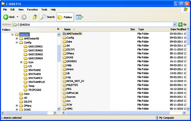
and the library and executable files necessary for the right execution of DAS showed in the following picture
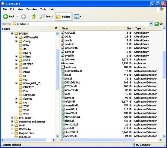
When the DAS starts it checks for the existence of the system sub folders necessary for the execution:
- '...DASxxx\LOG' - folder for the log files
- '...DASxxx\Data' - folder for the daily subfolders containing the measurement files
Usually the LOG and Data folder are already in the DAS root directory, but if they are not (for a previous cleaning operation) , when DAS is executed they are created and the user is warned with 2 messages. The messages are NOT MODAL (meaning that the DAS continue the execution without waiting for the user input):
.

.

.

.

Moreover DAS looks for its system files sequentially:
- Equipment.ini (Which equipment DAS has to control)
- wlstep.ini, (wavelength <-> steps)
- hardware.ini, (which NOVA SBC is installed)
- DasSysColor.ini, (colors for DAS GUI)
- DanboMap1.map, (Palette for Image visualization)
- GeoCoord.ini, (Coordinates of the station)
- Options.ini, (Parameters for the execution)
- ftp.ini, (parameters for FTP data back-up)
- Param.ini, (parameters for the CCD sensor and OMU thermoregulation, and CCD geometry)
- AMS.INI (Parameters for stepper motor's Controller)
- 'Equipment'.cfg, (parameter for CCD and HIRES Configuration)
if one or more of the above mentioned files is not present in the specific config directory or, in some case, the syntax of the file is wrong, the user is adviced.
Equipment.ini
if the file is not found in the .\\Config directory the following message is displayed:
\image html DAS_ErrEquip.png
...and DAS quits.\n

The user have to provide a valid 2Equipment.ini" file in the .\\Config folder\n

if the file is found in the .\\Config directory, but the value stored in it is not recognized by DAS
the following message is displayed:
\image html DAS_ErrEquip1.png
...and DAS quits.\n
The user have to correct the "Equipment.ini" file with an instrument code recognized by DAS \n
Once the DAS is started the "Equipment.ini" file can be modified with the  DASConfig --> Parameters --> \ref pg1
\verbinclude Equipment.ini
wlstep.ini
If the file is not found in the .\Config\'Equipment'\ folder the following message is shown
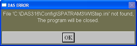
...and DAS quits.
The user have to provide a valid "wlstep.ini" file in the .\Config\'Equipment'\ folder
Once the DAS is started the wlstep.ini file can be modified with the DASConfig –> Parameters –> Page 2
###############################################
#                 WLSTEP.INI                  #
#  Wavelengths <--> Steps                     #
###############################################
# ------------------------------------------- #
#       by DanBo 28/08/2007 at 16:42:42       #
# ------------------------------------------- #
18
2823 36803
3337 24479
3850 12180
4358 0
4861 -12238
5332 -24031
5814 -35587
6282 -46808
6734 -57645
7201 -68842
7677 -80254
8195 -92674
8622 -102911
9023 -112526
9405 -121684
9758 -130148
10066 -137532
10358 -144533
hardware.ini
If the file is not found in the .\Config\ folder the following message is shown

...and DAS quits.
The user have to provide a valid "hardware.ini" file in the .\Config folder
Once the DAS is started the hardware platform can be changed through the DASConfig –> page
###############################################
#                  Hardware .INI              #
###############################################
#  Type of motherboard installed              #
# 0 = NOVA7892; 1 = NOVA6612; 2 = NOVA945GSE  #
###############################################
2
DasSysColor.ini
If the file is not found in the .\Config\'Equipment'\ folder the following message is shown

...and DAS will continue with the default (High Contrast) colors.
The user have to provide a valid "DasSysColor.ini" file in the .\Config\'Equipment'\ folder
Once the DAS is started the colors can be modified through the DASConfig –> Colors page
###########################################
#           DAS Default Color             #
#              by DanBo                   #
###########################################
# All these values can be modified, but   #
# DO NOT Exchange the order               #
###########################################
# Selected Buttons  BG                    #
255 255 111
# Unselected Buttons BG                   #
127 220 120
# UnSelected Buttons  FG                  #
0 0 0
# Forms and shell Background              #
87 80 72
# ACTIVE Labels Background                #
43 40 123
# ACTIVE Labels Foreground                #
255 255 255
# PASSIVE Labels Background               #
0 0 33
# PASSIVE Labels Foreground               #
255 255 255
# Capital Letters Labels Color	UP BG      #
147 158 189
# Capital Letters Labels Color	UP FG      #
0 0 0
# Radio Button BG      #
0 62 55
# Radio Button FG      #
255 255 0
###########################################
DanboMap1.map
If the file is not found in the .\PALETTE\ folder the following message is shown

...and DAS will continue ......
The user have to provide a valid "DanboMap1.map" file in the .\PALETTE folder
NOTE the different colors of the last warning, after the loading of the DasSysColor.ini file
     255       0       0
       0     255       0
       0       0     255
     255     128       0
       0     255     128
       0     128     255
     255       0     128
     255     128     128
     128     255       0
     128     255     128
     128       0     255
     128     128     255
........................
.....
until 256
GeoCoord.ini
If the file is not found in the .\Config\'Equipment'\ folder the following message is shown

DAS continue the execution, but......
Geographical Coordinates file for Evora station.
EVR     Station name (3 CHAR)
38.567     Latitude [ 90N, -90S]
-7.900     Longitude [ 0, 180 E],[-180 W, 0]
293.000     Altitude  [ masl]
0     TimeZone
Options.ini
File Options.ini is a very important system files. The parameters contained in it,affect the execution of the whole program. therefore a particular attention was placed in the error handling for the 'Options.ini' archive :
If the file 'Options.ini' is not found in the .\Config\'Equipment'\ folder the following message is shown

...and DAS quits.
The user have to provide a valid "Options.ini" file in the .\Config\'Equipment'\ folder
If the file is found but contains errors in the parameters values, a message like the one below is shown:

...and DAS quits.
For this particular case the LoadDB_Options procedure returned the error code 2. The whole set of errors code can be found in ERR_Option procedure
The user have to edit and correct the "Options.ini" file in the .\Config\'Equipment'\ folder
If the file is found but it was generated with a previous version of DAS the following message is shown:

...and DAS quits.
The user has to replace the file with a new valid one. Almost all the parameters in the 'Options.ini' file can be setted and modified operating on the DAS Configuration Panel–> Options page
\verbinclude Options.INI
Param.ini
If the file is not found in the ..\DASxxx\Config\'Equipment'\ folder the following message is shown

Param.ini contains the parameters regarding:
- the OMU and CCD thermoregulation
- the CCD window used
- the vertical binning applied to the CCD sensor
- the Maximum EXposure Time - MEXT
All these informations can be modified thrugh the Page 1 of the DAS Config.
###############################################
#                  Param.INI                  #
#    Main configuration file for SPATRAM      #
#                  equipment                  #
###############################################
# ------------------------------------------- #
#       by DanBo 04/12/2010 at 15:45:45       #
# ------------------------------------------- #
# CCD Temp (°C) ----------------------------- #
-20.0
# CCD Peltier Init Power X 10 (150 = 15.0)  #
300
# Optical Unit Target Temperature ------------#
20.0
# OMU Peltier Init Power X 10 (500 = 50.0)  #
802
# CCD Window (xstart ys xend ye) -------------#
0 0 1023 253
# Vertical Binning ---------------------------#
41
# Max Exposure Time s (=0 --> free exposure)  #
30.0
###############################################
CCD_Defect_Danbo.cor
\verbinclude ccd_defect_Danbo.cor
GeoDB.INI
Geographical Coordinates file.
the format is:
Station name ( Max 3 CHAR)
Latitude[90N,-90S] Longitude[0,180E],[-180W,0] Altitude(m/asl) TimeZone
BLQ
44.520 11.420 50.000 1
EVR
38.567 -7.900 293.000 0
LPA
35.520 12.570 4.000 1
TNB
-74.695 164.123 50.000 11
SPC
44.520 11.570 50.000 1
MTC
44.110 10.420 2200.000 1
STZ
42.416 25.633 500.000 2
VEN
45.431 12.311 3.000 1
AMS.INI
If the file AMS.ini is not detected in the folder "...\DASxxx\Config\'Equipment'\" the following windows is shown
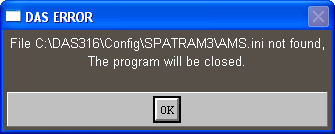
###############################################
#                  AMS.INI                  #
#    Main configuration file for AMS Devices  #
###############################################
# ------------------------------------------- #
#       by DanBo 27/11/2010 at 18:59:59       #
# ------------------------------------------- #
# Number of AMS                                #
3
# Input Mirror Stepper Motor - SM1            #
# SM1 Power (0 = 0A - 76 = 1.52A)             #
38
# SM1 Step (0=400s/r, 1=800s/r,2=1000/sr)     #
9
# SM1 Slope (0 - 255)                         #
20
# SM1 Speed Hz (PS = 125*(n+1), n=0,1..255)   #
255
# SM1  Multiplier                             #
6
# Grating Stepper Motor - SM2                 #
# SM2 Power (0 = 0A - 76 = 1.52A)             #
38
# SM2 Step (0=400s/r, 1=800s/r,2=1000/sr)     #
7
# SM2 Slope (0 - 255)                         #
20
# SM2 Speed Hz (PS = 125*(n+1), n=0,1..255)   #
255
# SM2  Multiplier                             #
4
# Filter Wheel Stepper Motor - SM3            #
# SM3 Power (0 = 0A - 76 = 1.52A)             #
38
# SM3 Step (0=400s/r, 1=800s/r,2=1000/sr)     #
3
# SM3 Slope (0 - 255)                         #
20
# SM3 Speed Hz (PS = 125*(n+1), n=0,1..255)   #
5
# SM3  Multiplier                             #
1
# Not Connected Stepper Motor - SM4           #
# SM4 Power (0 = 0A - 76 = 1.52A)             #
0
# SM4 Step (0=400s/r, 1=800s/r,2=1000/sr)     #
0
# SM4 Slope (0 - 255)                         #
0
# SM4 Speed Hz (PS = 125*(n+1), n=0,1..255)   #
0
# SM4  Multiplier                             #
0
# Zenith Axis  Stepper Motor - SM5            #
# SM5 Power (0 = 0A - 76 = 1.52A)             #
30
# SM5 Step (0=400s/r, 1=800s/r,2=1000/sr)     #
13
# SM5 Slope (0 - 255)                         #
20
# SM5 Speed Hz (PS = 125*(n+1), n=0,1..255)   #
255
# SM5  Multiplier                             #
4
# Azimuth Axis Stepper Motor - SM6            #
# SM6 Power (0 = 0A - 76 = 1.52A)             #
30
# SM6 Step (0=400s/r, 1=800s/r,2=1000/sr)     #
13
# SM6 Slope (0 - 255)                         #
20
# SM6 Speed Hz (PS = 125*(n+1), n=0,1..255)   #
255
# SM6  Multiplier                             #
4
# OFFSETS                                     #
# HMir, Mir0, Mir1, Mir2, Mir3, Mir4, Grat, FW#
14 0 0 0 0 0 0 0 0
Home Type Mode for Steppers                 #
SM1 SM2 SM3 SM4 SM5 SM6                       #
0 2 2 0 2 2
###############################################
'Equipment'.cfg
At booting, depending on the type of equipment setted, DAS looks for the CCD configuration file located in the "...\DASxxx\Config\'Equipment'\" folder. The CCD conf file has name: 'equipment'.cfg where equipment:
- SPATRAMPLUS
- SPATRAM2
- SPATRAM3
- LIS
- TROPOGAS
- GASCODNG1
- GASCODNG2
- GASCODNG3
- GASCODNG4
- if the file subfolder 'dcl' is not detected in the folder "...\DASxxx\" the following windows is shown
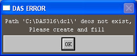
- if the file 'equipment'cfg is not in the "...\DASxxx\Config\'Equipment'\" subfolder:

- if an error occurr in reading the 'equipment'cfg

For these errors DAS continue the execution but without the CCD camera in operation.
To generate new configuration files for CCD and CCD driver the 'dcs.exe' application has to be executed
- directly selecting 'dcs.exe' in the "...\DASxxx" home directory.
In this case the program use its default configurations, so the file 'camera.cfg' is loaded and modified and stored. If this last has to be utilized for a specific equipment, the file 'camera.cfg' has to be copied in the "...\DASxxx\Config\'Equipment'\" subfolder and re-named in 'Equipment'.cfg. - through the CCD Setup command in DAS Configuration Panel –> Parameters –> Page 1 –> CCD Setup
. The program load the 'Equipment'.cfg archive if it is present in the folder or the 'camera.cfg' if not in the 'equipment' folder.
"Camera.cfg"
CameraConfig :
{
  Revision = 2.0;
  AD = 0;
  Activity = 22571;
  CCD = 120;
  CameraAddress = 0;
  CcdBackFront = 0;
  CcdOutput = 0;
  CcdTechnology = 1;
  DefectiveList = "";
  FilterWheel = 0;
  FilterWheelPortAddress = 0;
  FilterWheelPortType = 1;
  InterfaceAddress = 0;
  InterfaceLink = 4;
  InterfaceType = 6;
  LongCable = 0;
  PciIndex = 0;
  Platform = 28;
  Process = 0;
  ShutterHisteresys = 82;
  ShutterType = 0;
  TemperatureOffset = 0.0;
  TemperatureSpan = 1.0;
};
