- Introduction
- RS232 Connection and Transmission Protocol
- AMS Hardware Architecture
- AMS Commands
- AMS Connections
- Firmware Update
- Input/Output Port (Optically Decoupled)
- AMS Steps/round
- DAS AMS Functions
Introduction
AMS - Advanced Microstepping Controller - is a system for the control of the movements of small stepper motors (SM) since a maximum of 1.5 A for phase. 1 AMS can manage simoultanously 2 SM for the positioning as well as for the tracking
AMS implements the so called "opened ring" architecture, the quantization of the movement is given from the stepper motor of which is known the angular movement linked to an impulse.
The used technique in order to pilot the motors is called microstepping, Using this modality the angular step of the motor is setted via software, starting from the minimal value of 1/256 to ½ of the nominal step of the motor. Practically it is as to have a demoltiplier factor that can be setted electronically
The system moreover allows to vary the power engaged to the motors from a minimum of 30% (0.45A) to 100% (1.5A).
Other feature of this system is that one of being able to execute arbitrary tracking on both the axis.
At last one of the more interesting possibilities offered from this system is the possibility to connect in cascade unitl a maximum of 256 AMS, Since each AMS has an identity number ranging from 00 to FF, with only one serial port it should be possible to control a maximum of 512 motors.
Back to AMS2 (Advanced Micro Stepping) Controller
RS232 Connection and Transmission Protocol
AMS is controlled through one RS232 serial port with parameters: 19200, N, 8,1.
The transmission protocol employs only printable ASCII characters.
Each sent string is composed of:
- SOT - Start Of Text character = '$'
- EOF - End of Field character = '#'
- EOS - End Of String character = CR (13). Between EOF and CR there are 2 Hexadecimal digits that is the 8-bit CheckSum that is calculated from the SOT to the EOF (Excluded).
After the SOT there is always the address of the used AMS device (00-FF).
To any string sent to the AMS correspond a return string confirming the executed command. In case of normal command () the answer can be: - ACK if the command is executed without errors
- NAK if the execution of the command encoutered some errors The answer can be also something different from ACK or NAK. It could be a requsted status (i.e 0 if the positioning is already performed and the SM is stopped or 1 if the positioning is still on going).
COMMAND FORMAT $ Addr Command # Cksm CR ANSWER TYPE $ Addr ACK # Cksm CR
AMS answers after the execution of the command, the answer is received at the maximum after 20 mS.
The commands sent to the AMS present parameters for motor A and B; the first parameters are for motor A and the following for motor B
<CENTER>
Back to main
Back to AMS2 (Advanced Micro Stepping) Controller
AMS Hardware Architecture

The frequence F1, used for tracking, home and work is:
![\[ \qquad F1 = \frac{10E6}{n} \qquad (Hz)\]](form_52.png)
where n is a 32 bit value.
The frequence F2, used for the positioning is:
![\[ \qquad F2 = F1 (k + 1) \qquad (Hz)\]](form_53.png)
where k is the 8 bit value loaded in the multiplier.
<CENTER>
Back to main
Back to AMS2 (Advanced Micro Stepping) Controller
AMS Commands
    <CENTER>
\e Back \e to \ref main\n
\e Back \e to \ref amsmainpage
</CENTER>
In the following table are listed all the commands that can be sent to the AMS.
For each command are shown:
- The Decimal Code (Dec. Code column)
- The relative ASCII character (ASCII Char column)
- The numbers of parameters toghether with the format and the motor target (A or B) (Param/Format/Target column)
- The values that the parameters can assume (Param Range column)
- The operation on the Stepper Motors or AMS (Action column)
- The implemented function in DAS
Format Legend
- U8 = unsigned char - 1 Byte - 8 bits - 2 Hex Digits
- U16 = unsigned long - 2 Bytes - 16 bits - 4 Hex Digits
- U32 = unsigned long - 4 Bytes - 32 bits - 8 Hex Digits
For the Italian Version of the command please go to AMS Comandi (IT)
(Hex) | ||||||
PAR2 / U8 / B | Default 19H (0.5A), bit weigth = 0.02A | |||||
PAR2 / U8 / B | ||||||
PAR2 / U8 / B | Default 20 | |||||
Default 0 | ||||||
PAR2 / U8 / W_A PAR3 / U8 / H_B PAR4 / U8 / W_B | Default 0 | |||||
PAR2 / U8 / B | ||||||
PAR2 / U8 / B | ||||||
A(0) or B(1) | ||||||
PAR2 / U8 / B | ||||||
PAR2 / U8 / B | ||||||
A(0) or B(1) | ||||||
PAR2 / U8 / B | Default 0 | |||||
PAR2 / U32 / A PAR3 / U8 / B PAR4 / U32 / B | PAR2, PAR4: 00000000-FFFFFFFF | |||||
PAR2 / U32 / A PAR3 / U8 / B PAR4 / U32 / B | PAR2, PAR4: 00000000-FFFFFFFF | |||||
A(0) or B(1) | ||||||
PAR2 / U8 / B | Default 1 | |||||
A(0) or B(1) | ||||||
PAR2 / U8 / B | Default 7 | |||||
PAR2 / U8 / B | ||||||
PAR2 / U32 / AMS | 00000000-FFFFFFFF | |||||
Return 4 hex digits | ||||||
PAR2 / U8 / B | ||||||
PAR2 / U32 / B | 00000000-FFFFFFFF | |||||
PAR2 / U16 / AMS | PAR2:0000-FFFF | |||||
PAR2 / U8 / FPGA | PAR1 = reg address PAR2 = writing value | |||||
PAR1 = reg address | ||||||
PAR2 / U16 / AMS PAR3 / U16 / AMS | PAR2,PAR3:0001-FFFF |
<CENTER>
Back to main
Back to AMS2 (Advanced Micro Stepping) Controller
AMS Connections
In the following the connections allowing for the AMS's operation through a PC COM port, will be presented and explained.
Starting from the AMS device, the AMS Serial Interface is connected to the Signal Cable that is linked to the COM port of the PC.
The COM Interface can be used as for the AMS control as well as for the Firmware Update, but in this last case the Programming Cable has to be utilized.
If 2 or more AMSs have to be used (to a max of 256!!), more than 1 COM port have to be used or the same COM can be employed following the AMS Cascade connections.
Anyway the Firmware Update has always to be done on a single device.
<CENTER>
Back to main
Back to AMS2 (Advanced Micro Stepping) Controller
AMS Cascade connections
\image html AMS_Cascade2.jpg

\image html AMS_Cascade3.jpg
Back to AMS2 (Advanced Micro Stepping) Controller
AMS Serial Interface
\image html AMS_InterfaceCable.jpg
Back to AMS2 (Advanced Micro Stepping) Controller
Signal Cable
\image html AMS_SignalCable.jpg
Back to AMS2 (Advanced Micro Stepping) Controller
Programming Cable
\image html AMS_ProgCable.jpg
Back to AMS2 (Advanced Micro Stepping) Controller
Firmware Update
This procedure allows for the upgrade of the software in the microcontroller of the AMS.
The Programming Cable has to be connected to the AMS (that has to be OFF!!!) replacing the Signal Cable.
In addition a Jumper has to be placed to short the J1 switch.
The AMS can be swithed-on and only 2 of the 4 leds on the AMS will be on.
Now the application "FLASHSTA.EXE" has to be launched.
The window below will be shown.
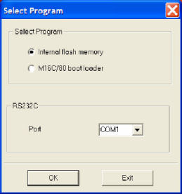
Now the COM port where is connected the AMS, has to be choosen.
This window will appear (if everything is OK)
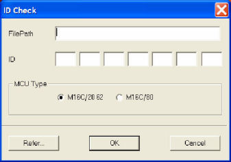
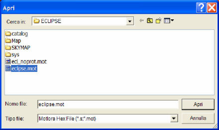
Now the button "REFER" has to be pressed and the desired *mot file has to be selected.
The previpous panel will be shown like:
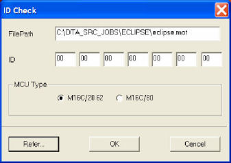
The button OK can be pressed and finally the programming window appears.
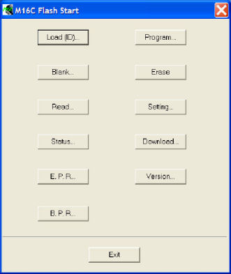
The button "E.P.R." has to be pressed in order to start the AMS programming.
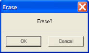
Pressing "OK" the programmation starts. At the end the operation will be verified
.
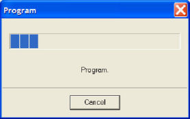
At the end of the process the programming panel will be showed; pressing EXIT the program quits.
Now the Signal Cable can be installed and it will be possible to work with the new software release.
Back to AMS2 (Advanced Micro Stepping) Controller
Input/Output Port (Optically Decoupled)
\image html AMS_IOPort.JPG "General Porpuse Opto Decoupled I/O Port"
- OOP[0:7]: Output Ports.
- IOP[0:7]: Input Ports.
- V_AN: Anode Voltage for the control of the IOPs (see figure AMS Anode).
- V_E: Emitter Voltage for the control of the OOPs(see figure AMS Emitter).
- A/D_TMP: Temperature sensor Input.
- A/D_PR: Pressure sensor Input.
- VCC: +5V 250mA MAX.
- POW: Supply voltage (250 mA MAX), It is the Power furnished to the AMS - Usually 12V
- GND: Ground.
For the different devices managed with the AMS Output port in the instruments managed by DAS, plese refers to page AMS OUTPUT Port Bits.
While for the Output ports all the 8 bits can be used, the Input ports has some bits that are employed for the HOME and WORK position of the Stepper Motors (se Table below)
For the specific use of the input port in the different version of the instrument managed by DAS, please refers to pag AMS INPUT Port Bits
Back to AMS2 (Advanced Micro Stepping) Controller
AMS Steps/round
For a standard stepper motor,the nominal value of stepping is 200 step/round. With the microstepping technology, this value can be increased. For AMSII the possible values of fractioning are reported in the table below:
Back to AMS2 (Advanced Micro Stepping) Controller
DAS AMS Functions
- DanBo procedures: for COM management
DanBo procedures: for AMS management
- AMS_assadd
- AMS_Default
- AMS_Power
- AMS_Step
- AMS_Slope
- AMS_Speed
- AMS_TrackOn
- AMS_TrackOff
- AMS_chkbitsts
- AMS_firmrev
- AMS_dirfin
- AMS_DoPos
- AMS_sendstep
- AMS_ReadStep
- AMS_TestPos
- AMS_AzzeraCoord
- AMS_wopto
- AMS_PWM
#########################################################################
AMS INPUT Port Bits
LIS, SPATRAM, GASCODNG1
AMS1: Address = 0
AMS2: Address = 1
Back to Input/Output Port (Optically Decoupled)
TROPOGAS, SPATRAMPLUS
AMS1: Address = 0
AMS2: Address = 1
AMS3: Address = 2
Back to Input/Output Port (Optically Decoupled)
AMS OUTPUT Port Bits
LIS, SPATRAM, GASCODNG2, GASCODNG3
AMS1: Address = 0
The SPATRAM Instrument doesn't exist anymore. It is replaced with the SPATRAMPLUS spectrometer that has 3 AMS devices allowing for using the alt azimuth platform (MIGE - Multi Input Geometry Equipment),
Back to Input/Output Port (Optically Decoupled)
GASCODNG1
AMS1: Address = 0
Back to Input/Output Port (Optically Decoupled)
TROPOGAS
AMS1: Address = 0
Back to Input/Output Port (Optically Decoupled)
SPATRAMPLUS
AMS1: Address = 0
Back to Input/Output Port (Optically Decoupled)
