The trigger of the camera becomes necessary when you must synchronize an outside event with the acquisition of the image.
Two trigger modes are possible:
Software mode
In the software way simply specifying the TRIGGER bit in the TaskSettings variable of the procedures DC_Open, _DC_Open, DC_OpenByConfig is enough. Enabling this way, every time we will use any acquisition procedure, the program will put himself waiting for the signal of trigger which will be sampled to the maximum speed. As soon as the trigger signal will be active the acquisition of the image will be realized. To be noticed that this mode, very simple to be realized and possible on every camera model, it has some limits as regards the synchronization precision of the trigger. The problem on the not efficient synchronization is due by speed of the processor and all the task which are in background to the operating system. This is a mode which can be used for the sampling of not critical events.
Hardware mode
The hardware trigger mode, he offers high speeds and high precisions in the synchronization, but it requires the knowledge specific of the hardware of the camera. In this mode it is possible to achive few nanoseconds to synchronize the camera to an external trigger.
Hardware trigger on CHROMA/CHROMA C3/Hires III/IV/Hurricane
We examine the circuit which control the trigger.
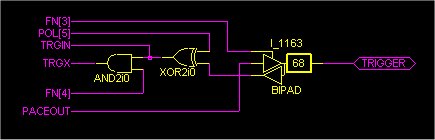
FN[3] this bit establishes if the trigger signal will be produced by the camera (output) or (input) will be read from this. Default is 0
POL[5] this bit establishes the polarity (activate low or high) of the trigger signal. Default is 0.
TRGIN signal sampled by the DC_Trigger procedure.
FN[4] bits which checks the enabling (1) of the trigger. Default is 0.
PACEOUT output of the pace-timer.
How is checking these bits possible?
For instance to activate the trigger and set up as active level zero I can write:
Before making the operations listed above, disabling the background activities with the DC_StopNow procedure is necessary, then it is possible to set the trigger up it and the acquisition loop is executed at last. Obviously with the disabled background the temperature loses his feedback, but he goes also considered that the camera has a big thermal inertia and so that a change of outside temperature has effect on the CCD, which is to the balance, several minute are necessary. In all the cases on 4-5 minutes suits restore the background task to verify and possibly correct the thermal balance of the sensor.
Later having set up the polarity of the trigger and having enabled it is necessary set up two important operating ways of the camera:
- Disabling the automatic cleanliness of the sensor is necessary.
- Disabling the automatic management of the shutter is necessary.
Using the procedures DC_SetMode and DC_GetMode as follows is enough to do that:
Can execute your cycle of acquisition now with the shutter synchronized perfectly with your outside event.// Okay now are almost ready! We must setup the shutter counter:DC_WRReg(6, 0xC0); // Mask shutter operation.DC_WRReg(5, 99); // The exposure time is equal to (n + 1) * 0.01 seconds.DC_Delay(1000); // The first time that initialize the shutter must expect this to complete his cycle.DC_WRReg(6, 0); // Unmask the shutter.
NOTE: An alternative to this code block is to take an image again to be used as setting of the shutter, obviously set up before possession the trigger.
ATTENTION: With the current (verified) LINUX versions (Mandrake 9.0 and SuSe 8.1), allocating big necessary memory blocks is not possible for a transfers in a single block of the image in DMA. Therefore the advantages offered by the FDL-PCI 2.0 (or higher) are not enjoyable.// I await that the trigger takes place.do{b = DC_GetStatus(7);}while((b & 0x1000) == 0);// The trigger fulfilled himself, the shutter opened, I wait now for the exposure end.do{b = DC_GetStatus(7);}while((b & 0x1000) != 0);DC_Delay(1000); // Wait the shutter (Time exposure value is 1 s)// Apply a delay now because the shutter, being an electromechanical device, does not instantaneously// close himself but necessity of a time which is proportional to his dimension.// For a 35 mm shutter a delay of 50 ms is ok.DC_Delay(50);// I execute any acquisition procedure, ignoring the parameter of the time of exposure and the mode.DC_FGetCCD(0, 0, mat, 0);// Now, without reseting up the shutter, I wait for the arrival of a new trigger and continue ....// IMPROVEMENT: if instead you have a FDL-PCI card with revision 2.0 or major, the previous code becomes:DC_ArmAcquisition(1.0, 0); // Arm the camera to take an image with an exposure time of 0.01 seconds.// When you want check if the camera is ready// When camera is ready you can retrive the image.DC_GetImage(mem, 0);
Hardware trigger on CHROMA C3 PLUS/C4/HiRes IV Plus
We examine the circuit which control the trigger.

FN[3] this bit establishes if the trigger signal will be produced by the camera (output) or (input) will be read from this. Default is 0
POL[5] this bit establishes the polarity (activate low or high) of the trigger signal. Default is 0.
TRGIN signal sampled by the DC_Trigger procedure.
FN[4] bits which checks the enabling (1) of the trigger. Default is 0.
FN[2] Bit used to check the trigger by software.
How is checking these bits possible?
For instance to activate the trigger and set up as active level zero I can write:
Before making the operations listed above, disabling the background activities with the DC_StopNow procedure is necessary, then it is possible to set the trigger up it and the acquisition loop is executed at last. Obviously with the disabled background the temperature loses his feedback, but he goes also considered that the camera has a big thermal inertia and so that a change of outside temperature has effect on the CCD, which is to the balance, several minute are necessary. In all the cases on 4-5 minutes suits restore the background task to verify and possibly correct the thermal balance of the sensor.
Later having set up the polarity of the trigger and having enabled it is necessary set up two important operating ways of the camera:
- Disabling the automatic cleanliness of the sensor is necessary.
- Disabling the automatic management of the shutter is necessary.
Using the procedures DC_SetMode and DC_GetMode as follows is enough to do that:
ATTENTION: With the current (verified) LINUX versions (Mandrake 9.0 and SuSe 8.1), allocating big necessary memory blocks is not possible for a transfers in a single block of the image in DMA. Therefore the advantages offered by the FDL-PCI 2.0 (or higher) are not enjoyable.// Now to take images with the trigger writing is enough.DC_ArmAcquisition(0.01, 0); // Arm the camera to take an image with an exposure time of 0.01 seconds.// When you want check if the camera is ready// When camera is ready you can retrive the image.DC_GetImage(mem, 0);
Hardware trigger on iCAM/iCAM II
ICAM it is a high-speed camera, the hardware implementation of the trigger is a critical function which is entirely developed by the FPGA of the camera, for this model a specific procedure exists.
Hardware trigger on Electra
Trigger on Electra system can be only in hardware, a rising edge signal (3.3V) applied onto pin 23 of the aux port can start the acquisition.
To enable or disable the trigger simply execute the following code:
