(Callback DB_KeyB_CB) The 6 pages for setting the DAS working parameters are showed.
Parameters
Page 1
The section Equipment Type of the page Parameters allows for the coiche of different instruments that can be managed by DAS:
- SPATRAM (SPectrometer for Atmospheric TRAcers measurements) - CGE-UE
- SPATRAM2 (SPectrometer for Atmospheric TRAcers measurements v. 2) CGE-UE
- SPATRAM3 (SPectrometer for Atmospheric TRAcers measurements v. 3) CGE-UE
- TROPOGAS (TROPOspheric GAScod) ....
- LIS (Lampedusa Island Spectrometer) ENEA
- GASCODNG1 (Gas Analyzer Spectrometer Correlating Optical Differences New Generation 1) CNR-ISAC
- GASCODNG2 (Gas Analyzer Spectrometer Correlating Optical Differences New Generation 2) CNR-ISAC
- GASCODNG3 (Gas Analyzer Spectrometer Correlating Optical Differences New Generation 3) CNR-ISAC
- GASCODNG4 (Gas Analyzer Spectrometer Correlating Optical Differences New Generation 4) CNR-ISAC
The selection of the new instrument is stored in the "..\DASxxx\Config\Equipment.ini" file, but to make effective the new setting the DAS has to be re-started
The section CCD & OMU Temp allows for the modification of the target temperature and power assigned to the Peltiers for the OMU as for the CCD Camera
- CCD target temperature
- CCD Init Peltier Power
- OMU target temperature
- OMU Init Peltier Power
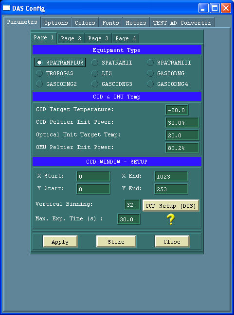
The section CCD Window allows for the choice of the CCD windows used and the setting of the vertical binning
- CCD window
- CCD vertical binning
The CCD Setup Button execute the DCS tool to select and setup the CCD Camera and Controller.
The Apply button (Callback ApplyChCB) has 2 different functions:
- If the CCD Setup has been executed copy the 'camera.cfg' file to the "..\DASxxx\config\'Equipment'\dcs" directory, init the camera (DB_InitCamera) reading the new configuration files and applies the new settings for the current session
- If the CCD Setup has NOT been executed init the camera (DB_InitCamera) reading the old configuration files and applies the new settings for the current session
The Store button (Callback WriteParaminiCB) has 2 different behaviours if the CCD Setup has been executed or not:
- If the CCD Setup has been executed copy the 'camera.cfg' file to the "..\DASxxx\config\'Equipment'\dcs" directory and write the new parameters in the file "..\DASxxx\Config\'equipment'\PARAM.INI",
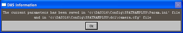
- if the CCD Setup has not been executed write the new parameters in the file "..\DASxxx\Config\'equipment'\PARAM.INI",
.
At the next DAS execution the new setting will be loaded.
The Close button (Callback CloseConfigCB) close the DAS_Config Window
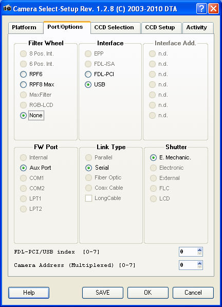
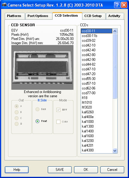
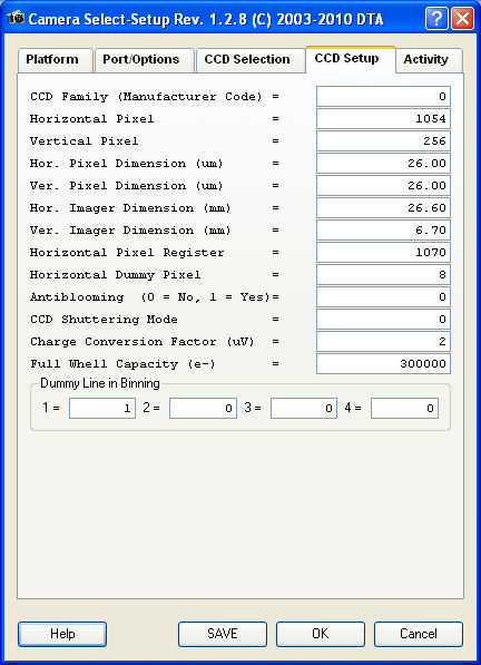
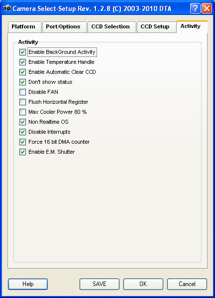
CCD Setup
The 'dcs' tool (DTA Camera Select-Setup) ,by default, read and write the 'camera.cfg' and 'dcl.cfg' in the ..\DASxxx\dcl directory and allows for the selection of the used platform (Page 'Platform')

Allow for the selection of the CCD controller:
- HiresIV for SPATRAMPLUS, GASCODNG1,2,3, TROPOGAS and LIS)
- HiresV for SPATRAM2, GASCODNG4
.
Page 2
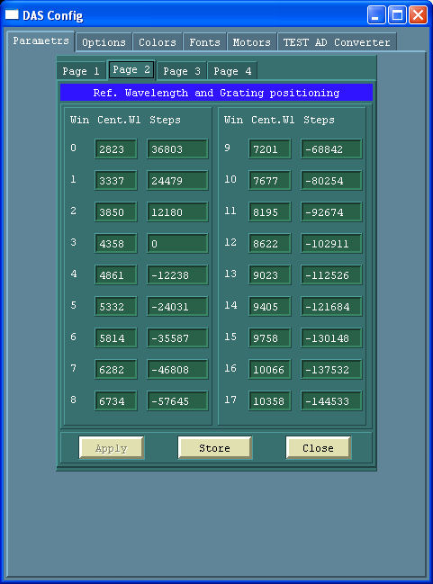
Until DAS306 the spectral windows were fixed and only with source code modifications should be possible to modify the Central Wavelength/steps and consequently the spectral windows of measurements.
Starting from DAS307 to DAS314 it is possible to modify the number of steps, but not the Central Wavelengths.
Moreover the Reference Position (4358 A, step = 0, with ID = 3) is fixed, forcing to have only 3 more window in the UV (2823, 3337, 3850).
With DAS315 and following, the Central wavelength and the steps can be modified In addition using the function Lookfor4358, it is now possible to assign the reference position 435.8 nm to any ID. If the reference position 4358 A, step = 0 has ID = 5,
2 more spectral window can be added in the UV region for example (2823, 3132, 3337, 3650, 3850).
This can be obtained
- using the above graphic interface
- modifying directly the 'wlstep.ini' file in the equipment config directory
NOTE - the 435.8 has to have step = 0 and the steps towards the UV must be negative (towards the visible positive)
Page 3
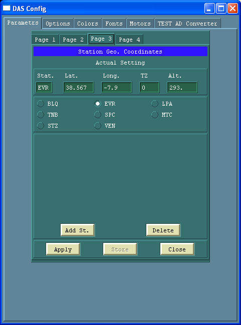
+++++++++++++++++++++++++++++++++++++++++++++++++++++++++++++++++++++++++++++++++
Page 4
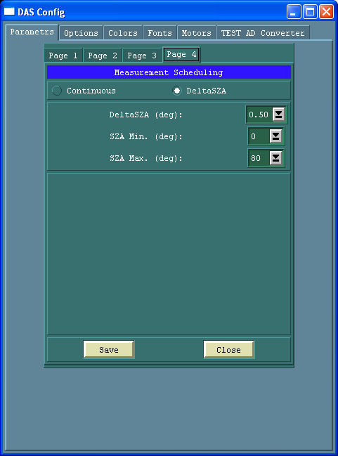
+++++++++++++++++++++++++++++++++++++++++++++++++++++++++++++++++++++++++++++++++
SECTION OPTIONS ********************************
Options
The Options Panel has 7 sub-pages:
- Options - Page 1
- Options - Page 2
- Options - Page 3
- Options - Page 4
- Options - Page 5
- Options - Page 6
- Options - Page 7
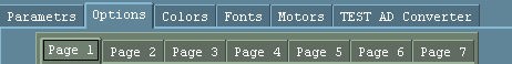
Almost all the options can be changed during the execution of the program in real time, so there is not a button applying the modification (as in the parameters page). The new settings are applied immediatly and will be lost at the end of the session. In order to mantain the modified settings also for futures runs of the program the button Store has to be used.

+++++++++++++++++++++++++ SECTION OPTION PAGE 1 +++++++++++++++++++++++++++
Options - Page 1
The first page allows for setting some options regarding mainly spectra and file storage (see below)
Section Saving Options
Saving mode
- ASCII: Spectra are saved in ASCII mode
- Binary: the binary mode save space on the disk (the best choice!!!)
File names
Free: DAS asks for the name of the file where the spectrum will be saved.
- Automatic: DAS assigns to the file names the format AAAYYMMDDxxx.ext
where:
- AAA = Name of the station (in the file "Path\DAS\Config\GeoCoord.ini")
- YY = year
- MM = month
- DD = day
- xxx = progressive number (0,1,....999).
- ext = bif or dat, according with the Spectra Saving Mode.
Each file will contain 50 spectra
Type of image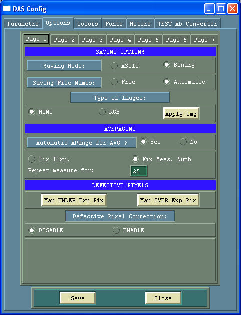
- AAA = Name of the station (in the file "Path\DAS\Config\GeoCoord.ini")
- Mono: Fixed
- RGB: The RGB mode is reserved for future realise.
Section Averaging
- Automatic AutoRange for AVG: Selecting "YES", when the averaging button is pushed (or the E_AVERAGE or the E_AVGCCDHor procedures) the Autoranging procedure is executed in order to set the Integration Time -TExp- utilized for the Averaging. Selecting "NO" as Exposure time the last Integration time used it will be utilized for the averaged measurements. ( The "Average" button is equivalent to the "GetCCD" one where the ARange button has to be used before the measurements )
Fixed Exposure Time or Fixed Number of measurements (In order to obtain highest S/N ratio - Fixed Exposure Time: the text box below report the total time over wich the measurements will be performed
- Fixed Number of measurements the text box below report the total number of measurements that will be performed for each scan
The Defective Pixel Section take into account that during the life of the instrument the CCD sensor can degrade his performances. In this regard the 2 push buttons Map UNDER Exposed pixels and Map OVER Exposed pixels can give the maps of the defective pixel. Defective pixel correction
- DISABLED ( in this case no correction is applied to the CCD Image) or
- ENABLED (the CCD image is corrected with a cubic spline interpolation over the defective pixels listed in the file "Path\DAS\Config\ccd_defect_Danbo.cor".
The Save Button writes the new settings in the "...\DASxxx\Config\'Equipment'\Options.ini" file
The Close Button close the DAS_Config window
Options - Page 2
The second page allows for setting some options regarding mainly CCD Dark removal, CCD Target temperature and System files (see below)
Remove dark from measurements
- Yes –> The dark is removed from the measurements
- No –> The dark is NOT removed from the measurements Dark source
- Full Frame –> if the previous option is estted on "Yes",the dark is removed from the measurements and rhe source is the full sensitive area of the CCD sensor (this means that a DARK measurement is carried out before the LIGHT measurement).
- Blind Pixels –> if the previous option is estted on "Yes",the dark is removed from the measurements and rhe source are the 30 Blind Pixels on the right of the CCD sensor (this means that the DARK measurement is not necessary).
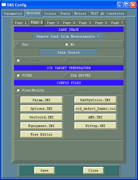
CCD Target Temperature
- Fixed –> The CCD target temperature remains always that is setted in the Parameters page
- SZA Driven –> The CCD target temperature varies with the Solar Zenith Angle. The temperature starts decreasing when the SZA is higher tham 80�
Config Files
- 5 of the 6 buttons can be used for the editing of the configuration files for DAS:
- The last button is a free editor
The Save Button writes the new settings in the "...\DASxxx\Config\'Equipment'\Options.ini" file
The Close Button close the DAS_Config window
Options - Page 3
The third page allows for setting some options regarding mainly the plot window (see below)
X Axis Units
- PIXEL
- WAVEL[A]
- WAVEL[nm] Display PLOT after measurement ?
- NO
- Yes
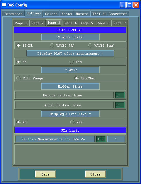
Y Axis
- Full Range (0 - 65535)
- Min//Max of the measurement
Hidden lines
The CCD sensor could be not homogeneously illuminated, so some lines could present a mean value too low and if all the line are plotted could not be possible to appreciate the quality of the measurement. Depending on the vertical binning, the numbers of lines to be plotted, after and before the central one, can be selected.
- Before Central Line
- After Central Line
Display Blind Pixel?
The CCD sensor in use (Marconi CCD3011-Bi) has 1054x256 pixels, but only 1024 are illuminated; the remaining 30 are blind and can bu used for the quantification of the read current
- NO
- Yes
SZA Limit
The spectrometer will perform measurements for values of Solar Zenith Angles <= X
The Save Button writes the new settings in the "...\DASxxx\Config\'Equipment'\Options.ini" file
The Close Button close the DAS_Config window
+++++++++++++++++++++++++++++++++++++++++++++++++++++++++++++++++++++++++++++++++++++++++
Options - Page 4
The third page allows for setting some options regarding the daily data back-up and OMU Thermoregulation (see below)
Perform FTP Back-Up
Select if the Back-up will be performed during the period of inactivity of the instrument (when the SZA is greater than the fixed values)
- Yes
- NO Server FTP Address:
Username - for FTP accessing PWD - for FTP accessing The Save FTP Button writes the new settings in the file
The TestFTP Button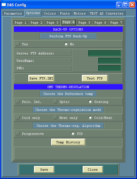
Choose the Reference temp
The OMU reference temperature can be chosen between:
- Pelt. Int. (The average of the left and right temperature for the main OMU Peltier)
- Optic (temperature of the sensor outside the monochromator but inside the OMU)
- Grating (temperature of the sensore inside the monochromator and near to the grating)
Choose the Thermo-regulation mode
The thermo regulation mode can be chosen....
- Cold only
- Heat only
- Cold//Heat
Choose the Thermo-reg. Algorithm ...and also the used algorithm
- Progressive
- PID (Proportional, Integer, Derivative)
The Save Button writes the new settings in the "...\DASxxx\Config\'Equipment'\Options.ini" file
The Close Button close the DAS_Config window
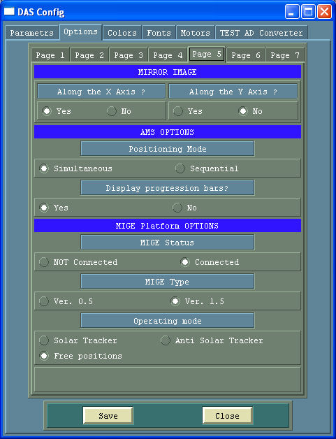
Options - Page 5
Section Mirror Image
Along the X Axis ?
- YES: The spectra will be mirrored
- NO : The spectra will remain unmirrored
Along the Y Axis ?
- YES: The spectra will be mirrored
- NO : The spectra will remain unmirrored
Section AMS Options
Positioning mode
- Simoultaneous: The stepper motors will move all at the same time (/ref SD_Position)
- Sequential : The steppers motor will positioning sequentially. First the stepper for the input mirror, then the one for the grating, for the filter wheel, Zenith and Azimut (when the AltAzimuth Platfor is connected.
Display Progression Bars
- Yes: The progression bars are displayed during the positioning.
- No : The progression bars are NOT displayed
Section AltAz Platform Options
- Solar Tracker: The AltAzPlatform acts as a solatr tracker
- Anti Solar Tracker: The AltAzPlatform Position itself in the complementary sun angle
- Free Positioning: The AltAzPlatform can be positioned free
The Save Button writes the new settings in the "...\DASxxx\Config\'Equipment'\Options.ini" file
The Close Button close the DAS_Config window
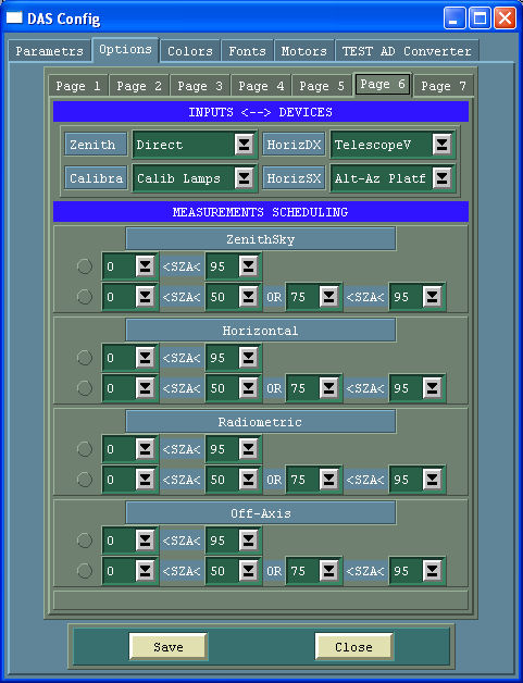
Options - Page 6
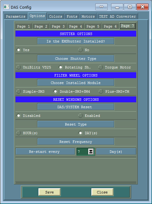
Options - Page 7
Colors
The page Colors allows for the modification of the Colors used by DAS for the visualization of the widgets
The user has to select the radio buttons for the components to be changed and then moving the RGB scroll bars the colors can be fixed
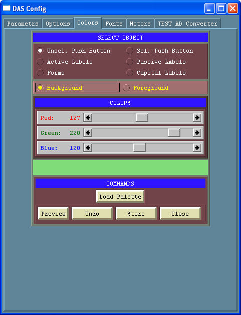
In addition with the button "Load Palette" can be loaded the different color tables in the folder "..\\Palette".
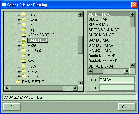
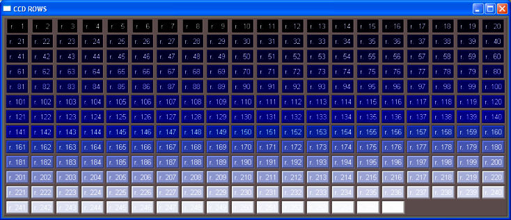
these table are used to distinguish the different lines of the CCD sensor (till 256)
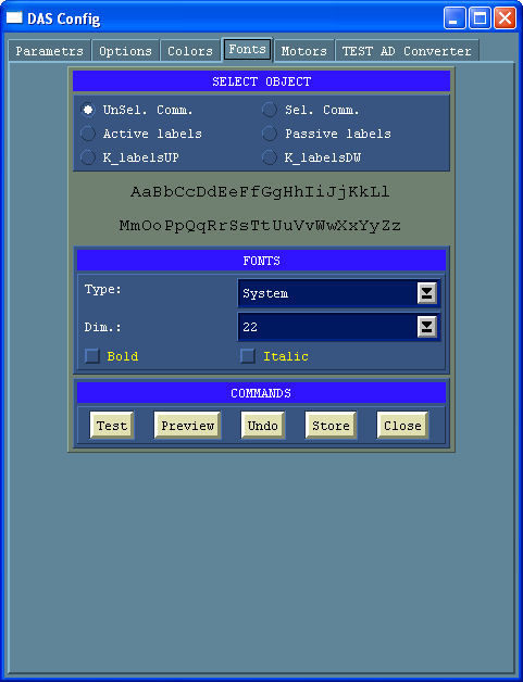
Fonts
The page Fonts allows for the modification of the DAS Fonts
## SECTION STEPPER MOTORS
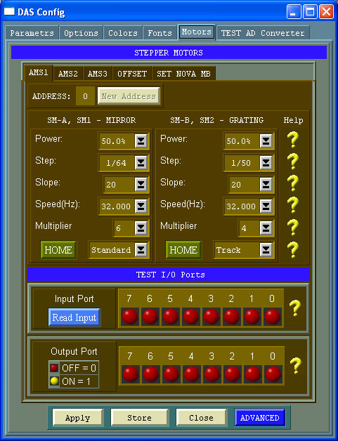
Steppers Motor
The page Motors allows for testing and changing the parameter of the AMSs devices (the drivers of the stepper motors)
In this panel there are other sub-pages equal to the number of the AMS installed on the equipment or specified in the AMS.INI system file.
In addition 2 more pages are available for:
AMS1
The AMS1 Controller drives:
- Motor A - Stepper for the tilted rotating mirror (selecting the radiation inputs)
- Motor B - Stepper for the scanning grating
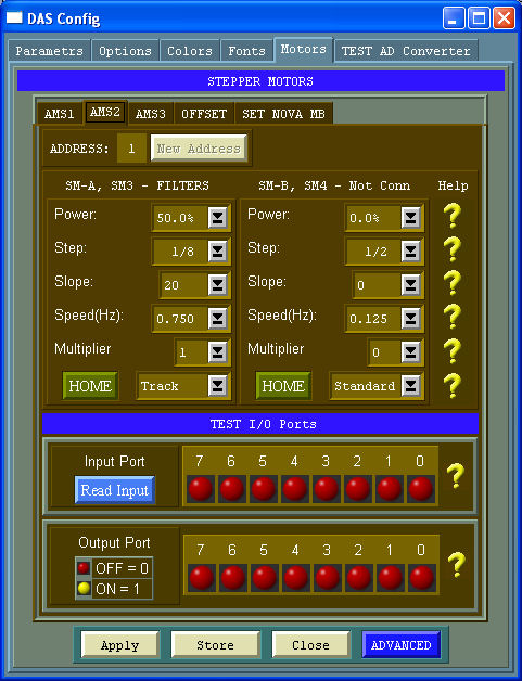
AMS2
The AMS2 Controller drives:
- Motor A - Stepper for the filter wheel
AMS3
The AMS2 Controller drives:
- Motor A - Stepper for the zenith axis of the external scanning device (MIGE)
- Motor B - Stepper for the azimuth axis of the external scanning device (MIGE)

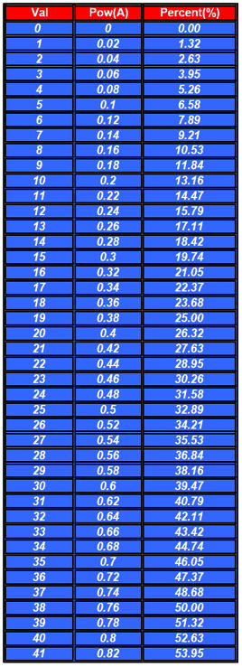
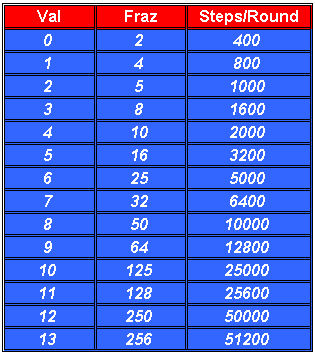
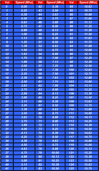
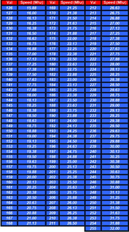
For each motor can be selected:
- Power
- Step/Rounds
- Slope
- Speed
In addition in the bottom panel the push buttons can be used to test the OptoInsulated ports of each AMS (AMS OPTO)
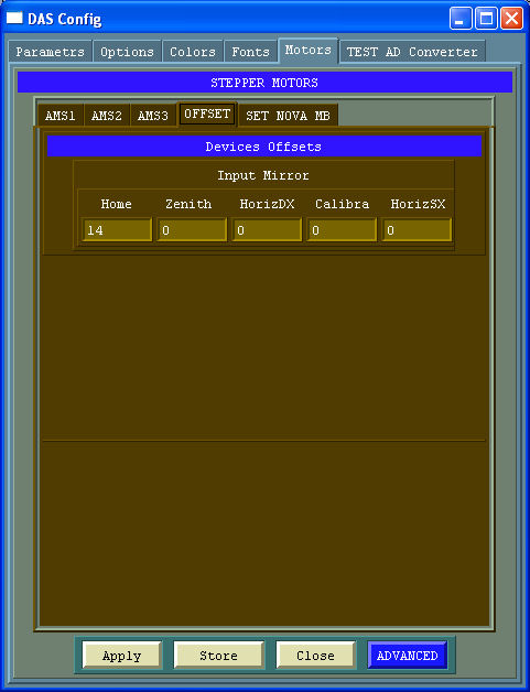
OFFSET
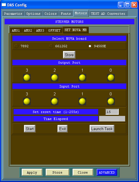
SET NOVA MB
Power
Step/Rounds
Speed
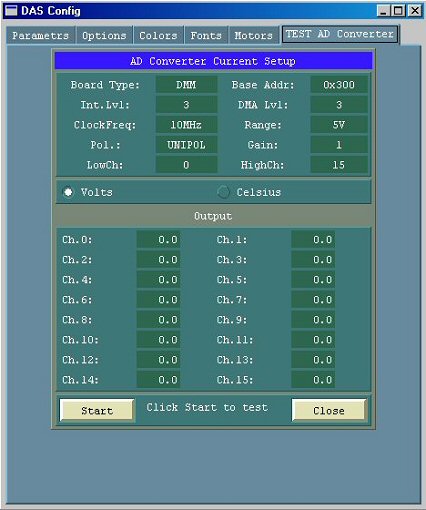
TEST AD Converter
The page TEST AD Converter can be used for testing the PC104 AD Converter that through the AD590 and TAD read the temperatures inside the equipment