MIGE OverView
The MIGE device is composed by a rotating platform with an excursion of 2pi that allows for the investigation of the entire azimuth plane. A rotating input mirror, with a narrow field of view, can collect the diffuse or direct solar radiation in the whole zenith plane. The whole equipment is placed under a dome of fused silica to avoid undesired effects of light reflexes and to allow for measurements in the UV spectral region.
The MIGE allows for measurements of spectral sky radiance in different configurations (off-axis, almucantar, limb) in order to be able to derive both the total column and the vertical profile of some optically thin atmospheric compounds (i.e. bromine monoxide - BrO, formaldehyde - HCHO, SO2). In addition, MIGE is developed in order to perform measurements of the spectral sun radiance that, after determining suitable calibration coefficients, can be compared with the AERONET radiance data. At the same time corrections of AERONET data from the NOx signal can be provided.

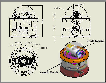
Figure 1 shows the executive designs for the MIGE and the 2 main units composing the MIGE: the zenith module (ZM) and the azimuth one (AM) are highlighted. It has to be remembered that the complete development work was done at the Geophysics Centre of the University of Evora. The design includes also the development of the optical layout (mirrors and optic fibres) and the choice of the right devices as bearings, belt and stepper motors to be used in the device. The spatial dimensions of the MIGE equipment are very small: the external cylinder, containing the AM, has a diameter of 200mm, and the total height of the equipment is of 220mm. In the ZM, the optic system contained in the zenithal pipe has a focal of 60mm. The optical fibre carrying the signal to the SPATRAM instrument is a standard optical fibre cable containing 50 fused silica core each one with a diameter of 0.05mm. The fibre, in terms of its termination, was adapted in order to match the mechanical requirements of the MIGE. Due to the focal length of the optical system it was chosen an optical fibre with numerical aperture (NA) of 0.22.

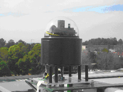
In Figure 2 the MIGE device in its work configuration is shown. The installation of the MIGE in the roof of the laboratory containing the SPATRAM instrument, ensure the possibility to carry out measurements in off-axis configuration along many azimuthal directions since the horizon line is almost completely free.
Optical Layout
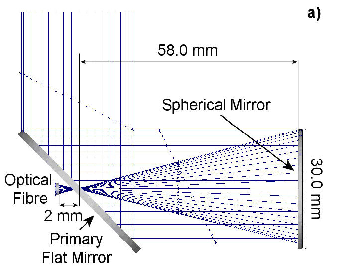
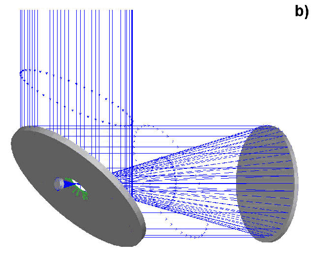
In Figure 3a and 3b the optical layout of the MIGE device is illustrated: the light entering the MIGE, is reflected by the flat mirror tilted at 45° towards the spherical mirror. This last focus the light beam in the point placed 2 mm behind the flat mirror entering the optical fibre.


Mechanical Designs
Electrical Wirings
MIGE - Prototype
MIGE - Silver
